A kind of engine oil gas separator

An oil and gas separator and engine technology, which is applied to engine components, machines/engines, mechanical equipment, etc., can solve the problems of large resistance, large filter element resistance and high separation efficiency, and achieves reduced resistance, better oil and gas separation effect, and reduced system The effect of resistance

Active Publication Date: 2012-02-15
CHERY AUTOMOBILE CO LTD
View PDF0 Cites 3 Cited by
  • Summary
  • Abstract
  • Description
  • Claims
  • Application Information

AI Technical Summary

Problems solved by technology

[0003] These two oil-gas separators are characterized by low resistance and maintenance-free, but the disadvantage is low separation efficiency. There are also a small number of engines that use filter-type oil-gas separators, which are characterized by high separation efficiency and large resistance, especially the adhesion of a certain amount on the filter element. After the engine oil is used, the resistance of the filter element will be greater

Method used


Image

  • A kind of engine oil gas separator
  • A kind of engine oil gas separator

Examples


Embodiment Construction

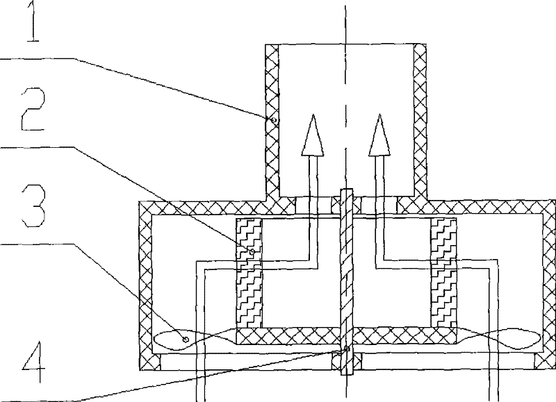
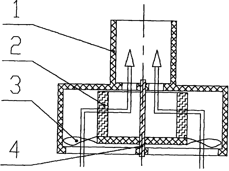
[0010] As shown in the figure, the engine oil and gas separator has a housing 1, a blade 3, a filter element 2, and a rotating shaft 4, wherein the blade 3 and the filter element 2 are fixed on the rotating shaft 4, and the rotating shaft is mounted on the housing 1.

[0011] The blade 3, the filter element 2, and the rotating shaft 4 are all rigidly connected, and the filter element is located above the blade. The housing 1 is provided with a rotating shaft installation hole. The housing can be arranged on the valve chamber cover, timing cover or crankcase, or integrated with the valve chamber cover, timing cover or crankcase to make the engine structure More compact.

[0012] The arrow in the figure shows the flow direction of the crankcase gas. The crankcase gas first drives the filter element 2 to rotate around the rotating shaft 4 through the blades 3, while the crankcase gas flows radially, resulting in cyclone separation, which can separate the larger oil droplets in the cr...


PUM


Abstract

The invention relates to an engine oil-gas separator, which has high oil-gas separation efficiency and small resistance. Technical solution: an engine oil-gas separator, characterized in that it has a blade, a filter element, and a rotating shaft, wherein the blade and the filter element are fixed on the rotating shaft, and the rotating shaft is mounted on the housing. The invention combines the structural characteristics of the filter element type and the cyclone type oil-gas separator. After the crankcase gas is separated by the blades for the first time, it is separated by the filter element for the second time. Breaking away from the filter element under the action of centrifugal force can effectively reduce the resistance of the filter element, achieve the best oil and gas separation effect, and reduce the system resistance at the same time.

Description

Technical field [0001] The invention relates to an engine crankcase ventilation system, in particular to an engine oil and gas separator. Background technique [0002] Existing engine crankcase ventilation systems mostly use labyrinth or cyclone oil and gas separators. The labyrinth oil and gas separator realizes oil and gas separation: when the oil and gas mixture passes through the labyrinth, due to inertia, small oil droplets in the mixture will hit the wall of the maze and flow down along the wall, and the gas in the mixture will be smooth Enter the crankcase ventilation system through the labyrinth. The separation method of the cyclone oil and gas separator is similar to that of the labyrinth oil and gas separator, except that small oil droplets in the mixed gas encounter the wall of the oil and gas separator under the action of centrifugal force and flow down the wall. [0003] The characteristics of these two oil and gas separators are low resistance and maintenance-free. ...

Claims


Application Information

Patent Timeline
Patent Type & Authority Patents(China)
IPC IPC(8): F01M13/04
Inventor 高建鹏
Owner CHERY AUTOMOBILE CO LTD
Why Eureka
Try Eureka