
Vertical shaft giant energy and energy-collecting wind-power water drawing machine

A wind turbine and vertical shaft technology, which is applied in the field of new vertical shaft wind water lifting units, can solve the problems of low active control ability, difficult driving, and difficult effective application, etc., and achieve the effect of realizing the design level of the output capacity of a single machine.

Inactive Publication Date: 2009-02-11
陈晓通
View PDF0 Cites 3 Cited by
  • Summary
  • Abstract
  • Description
  • Claims
  • Application Information

AI Technical Summary

Problems solved by technology

[0005] There is also a design that arranges the blades on the wind force plate that rotates around the vertical axis, forms a closed state against the wind when it faces the wind, and is naturally blown up when it reaches the side of the windward side, but its shape is bulky, and it is difficult to blow it up and turn it with the wind when the wind is not strong. side blades, their active control ability is not high, making it difficult to effectively apply
[0006] There are also vertical shaft wind turbines that are designed with a mechanically driven rotation device installed inside the vertical shaft to realize the cycle of one side of the blades arranged on the rotating wind plate being closed and the other side being opened, but it can only be realized by 2 in the same height plane. It is difficult to drive 3-8 rotating wind panels at the same time, and the common design of 4-8 rotating wind panels is a necessary condition for efficient and sufficient wind collection to realize the design of huge energy output.

Method used


Image

  • Vertical shaft giant energy and energy-collecting wind-power water drawing machine
  • Vertical shaft giant energy and energy-collecting wind-power water drawing machine
  • Vertical shaft giant energy and energy-collecting wind-power water drawing machine

Examples


Embodiment Construction

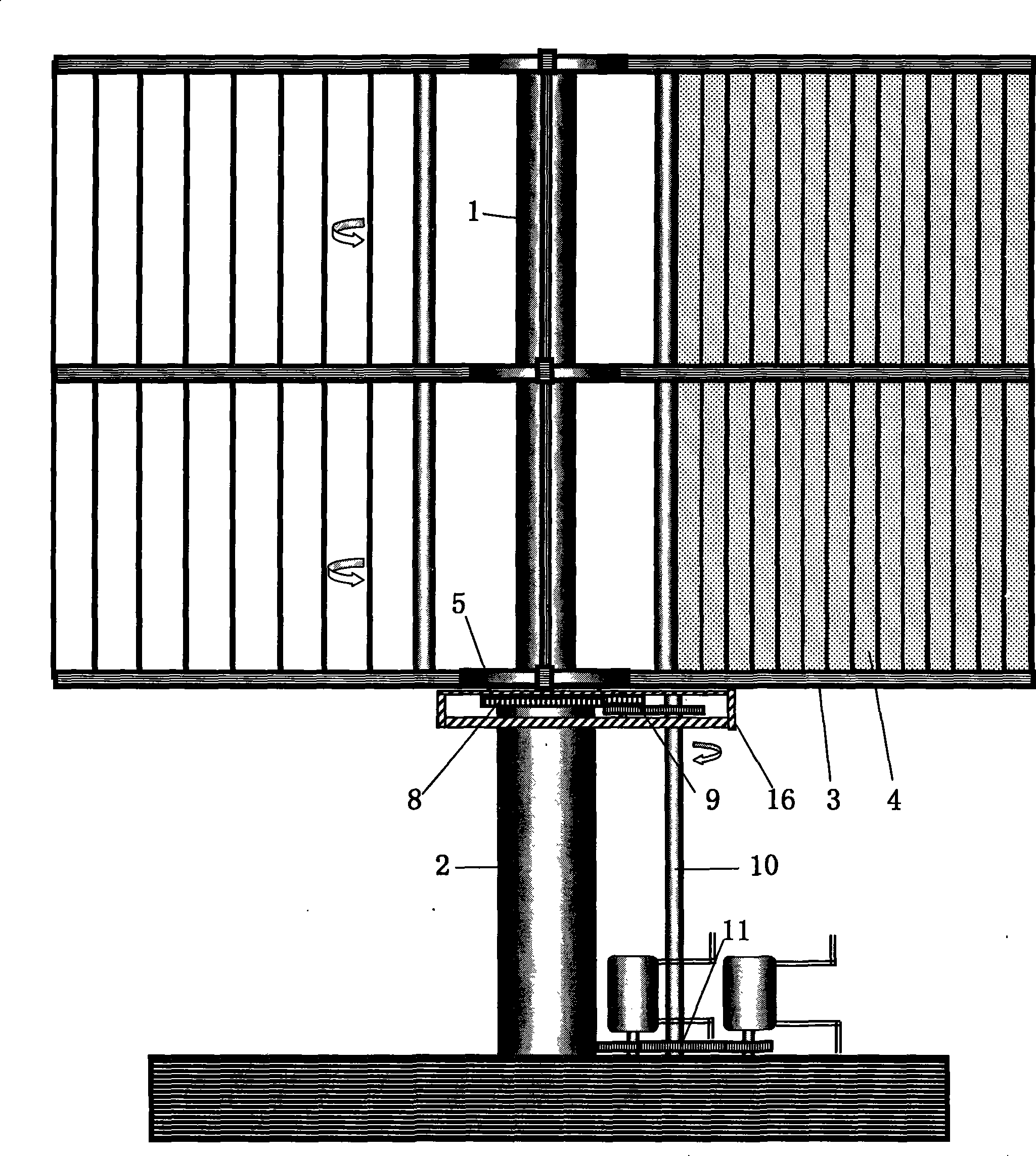
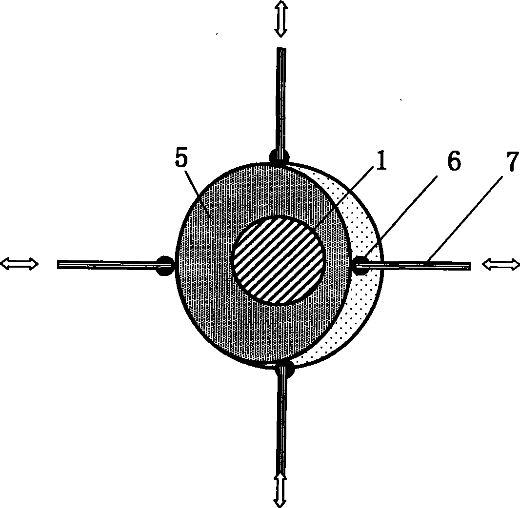
[0029] combine figure 1 , 2 , 6) It can be seen that when the vertical axis giant energy wind-driven water lifting unit is working against the wind, it first needs to measure the direction of the wind force, and then determine and adjust the direction of the flat part of the wind-facing guide rail disk 5 according to the direction of the wind force, so that it can reach the operating position of each rotating wind force plate 3 At the same time, the windward inverter plate 4 on it is closed due to the cooperative drive of the rolling wheel 6 and the push-pull rod 7, and the direction of the convex part of the windward guide rail disk 5 can make the operating position of the rotating wind force plate 3 in place and then unfold. The installed push-pull spring realizes the reset, and when it is close to the downwind windward angle, the windward inverter board gradually expands, and gradually shrinks after reaching the vertical wind direction.

[0030] Through the above process,...


PUM


Abstract

The invention relates to a vertical shaft giant energy and energy collecting wind power water elevator group, of which a giant energy unit is composed of a vertical shaft, a rotational wind power plate, an upwind inverting plate, a yawing guide disc, a water elevator tool, and the like, and which can realize giant output capacity and cascade output capacity and regulation thereof. The water elevator group brings in the operation mode of a vertical wind power turbine into the determination and regulation of the wind power direction for the first time; the water elevator group can lead the rotational wind power plate to realize fully-closed wind collection and super low resistance rotary operation, thus forming an unprecedented giant output capacity design; the water elevator group as well can control the operation of partial or full opening of the upwind inverting plate on the rotational wind power plate, thus realizing the advantageous effects of the regulation brake of upwind change and resistance to impact of typhoon; the water elevator group has simple structure and convenient disperse transportation as well as a giant wind collecting area; a unite concentration output power formed by a plurality of vertical shaft giant energy wind turbines connected in series is combined with the water elevator tool to form an energy collecting unit, thus realizing the combination in series of the vertical shaft wind power unit; the co-occurrence becomes a watershed for wind power water elevation to realize extensive, efficient, scaled development.

Description

technical field [0001] The invention relates to a novel vertical-axis wind-driven water-lifting unit, in particular to a vertical-axis wind-driven water-lifting unit designed with a wind-facing guide rail plate control structure to realize unprecedented huge energy output capacity and an energy-gathering unit formed by series connection thereof. Background technique [0002] At present, most of the wind-powered water-lifting equipment adopts the horizontal-axis blade windward rotary wind turbine as the water-lifting power, but its single-machine wind collection area and output capacity are relatively low, and output control and wind control are difficult, and it is difficult to meet the water-lifting demand. Giant energy design requirements. [0003] The vertical axis wind turbine has unique advantages that other types of wind turbines cannot replace, and can meet the flexible setting requirements of a single wind power water pumping machine. It has a simple structure, a sin...

Claims


Application Information

Patent Timeline
IPC IPC(8): F03D9/00F03D7/06F03D3/02F03D9/28
CPCY02E10/74Y02P80/10
Inventor 陈晓通
Owner 陈晓通
Learn More