
High precision refraction static correction data inversion method

A refraction static correction and data inversion technology, applied in the field of high-precision refraction static correction data inversion, can solve the problems of not using refraction first arrivals, heavy collection workload, high cost, etc., to improve accuracy, expand application range, adaptable effect

Inactive Publication Date: 2009-02-11
BGP OF CHINA NAT GASOLINEEUM CORP
View PDF0 Cites 23 Cited by
  • Summary
  • Abstract
  • Description
  • Claims
  • Application Information

AI Technical Summary

Problems solved by technology

[0017] However, the large refraction-time-depth curve method does not use the refracted first arrival wave of the production shot, and needs to collect large refraction data along the survey line alone, which requires a large collection workload and high cost

Method used


Image

  • High precision refraction static correction data inversion method
  • High precision refraction static correction data inversion method
  • High precision refraction static correction data inversion method

Examples


Embodiment Construction

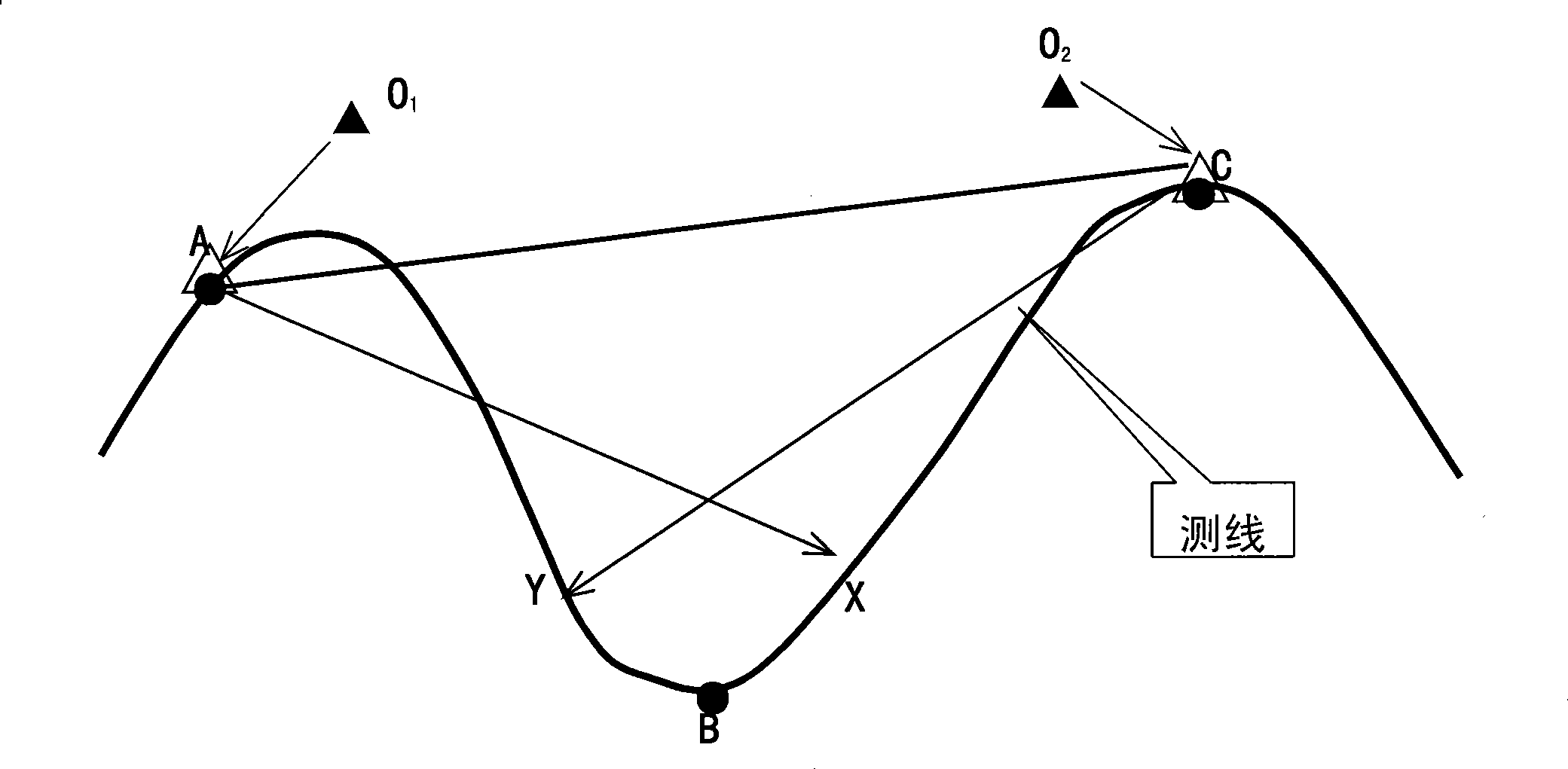
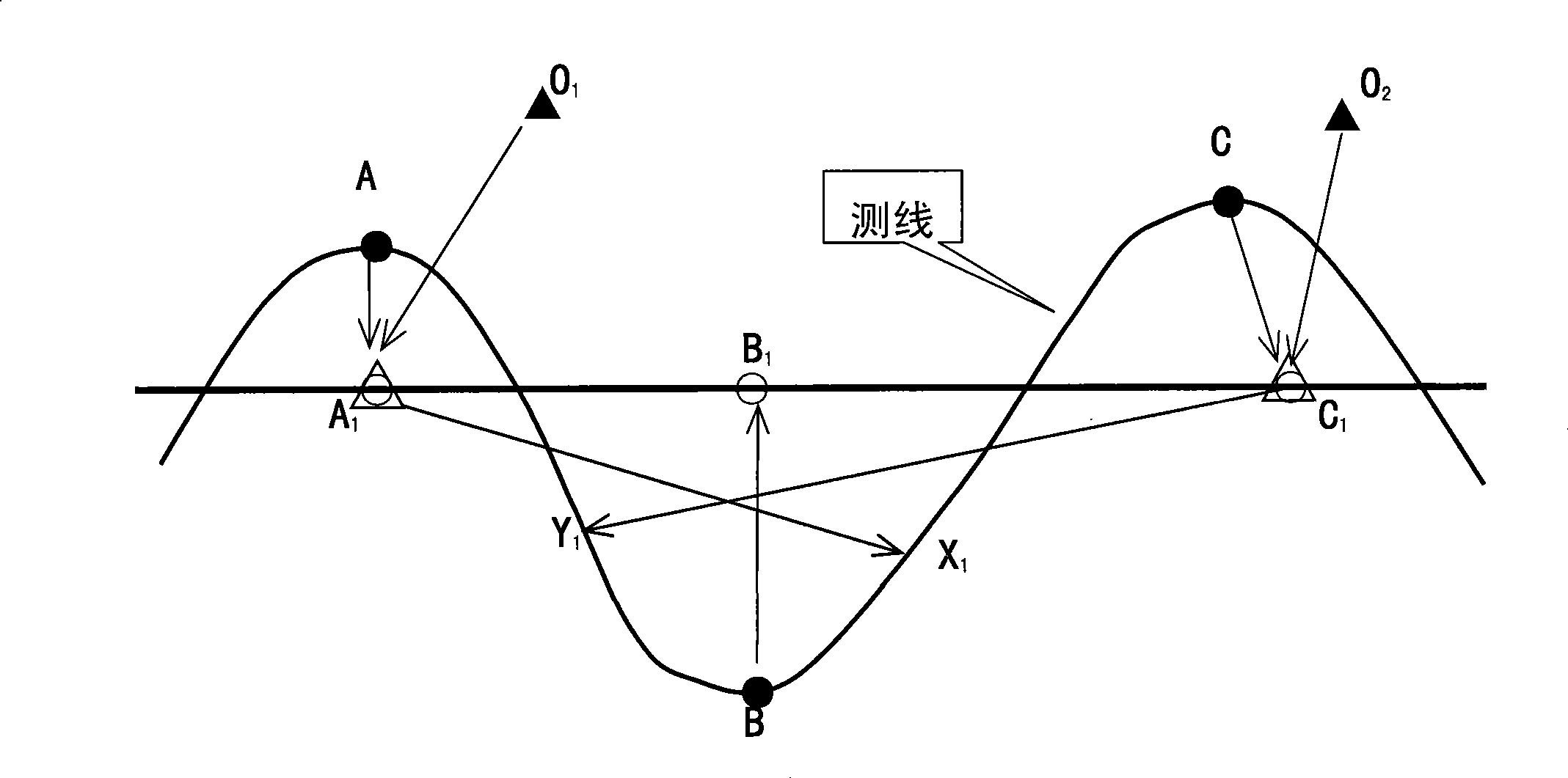
[0054] Embodiment 1 of the present invention. The surface survey adopts 13 production gun drawing lines for calculation, with a line spacing of 1.5km; 8 large refraction lines are laid out, with a line spacing of 3km, and 6 of them coincide with the three-dimensional production gun drawing lines for comparison of results and verification of the production gun calculation accuracy. Seven micro-logging wells are deployed in the area, and the micro-logging wells provide surface velocity and control point depth data. This method shows that the large refraction of the 6 coincident lines and the results of the first arrival of the production shot are compared, and the delay time and the bottom interface of the low-velocity layer of the two basically coincide. The statistics of the elevation error of the bottom interface of the delay time and low-velocity layer: the arithmetic mean value of the delay time error is 0.32ms, and the absolute mean value of the error is 1.77ms; the arith...


PUM


Abstract

The invention relates to a geophysical prospecting method which is a high-precision refraction static correction data inversion method. The method comprises the steps: the production shot first arrival data of an earthquake work area are collected; the refraction wave delay time is calculated out through the following steps; and the data of micro logging control points and the information of refraction delay time are used for obtaining the time-depth curve of the low deceleration layer of the work area. Micro logging control points provide a target layer depth (HD), a refraction result offered delay time tD, a comprehensive tD(HD) curve and a conversion tD curve, thereby obtaining a reliable surface structure model and a high-precision low deceleration zone static correction result profile map. The invention has the advantages that the depth curve constrains and inverses the delay time when the high-precision low deceleration layer is used; the depth errors caused by the inaccurate velocity are eliminated; the application condition is wide; the adaptability is strong; and the result precision is finally improved.

Description

[0001] Field [0002] The invention relates to a geophysical exploration method, which is a high-precision refraction static correction data inversion method used in seismic data processing. Background technique [0003] Seismic exploration is the main geophysical method used to find oil and gas fields. It uses explosives and other methods to generate artificial earthquakes on the ground. Special instruments collect seismic signals at a series of observation points. After indoor data processing and interpretation, effective information is extracted, and oil and gas investigations are carried out. related geological structures. [0004] In order to obtain seismic data with a high signal-to-noise ratio, the current seismic technology generally adopts the method of "multiple coverage". Point-detection point distance is different. During the data processing, high-quality results profiles are obtained through the processes of sampling collection—static correction—velocity analysi...

Claims


Application Information

Patent Timeline
Patent Type & Authority Applications(China)
IPC IPC(8): G01V1/36G01V1/37
Inventor 陈振声闫杰
Owner BGP OF CHINA NAT GASOLINEEUM CORP
Learn More