Light guide plate of backlight unit with patterns

A backlight unit and light guide plate technology, applied in light guides, optical components, optics, etc., can solve problems such as reduced productivity, uneven light scattering, screen moiré, etc., to prevent the appearance of dark lines, prevent poor appearance, and reduce changes volume effect

Inactive Publication Date: 2009-02-11
주비젼텍 +1
View PDF0 Cites 50 Cited by
  • Summary
  • Abstract
  • Description
  • Claims
  • Application Information

AI Technical Summary

Problems solved by technology

[0008] First of all, the mechanical cutting method using diamond has the following disadvantages: its speed is relatively slow, which reduces productivity, light cannot be scattered uniformly due to the roughness of the processed surface, and the reproducibility of reproducing the desired pattern form as it is is reduced
However, because it only adjusts the Y-axis displacement (displacement) by adjusting the size of individual graphics and the distance between X-axis and Y-axis between individual graphics, low-brightness dark lines (dark

Method used


Image

  • Light guide plate of backlight unit with patterns
  • Light guide plate of backlight unit with patterns
  • Light guide plate of backlight unit with patterns

Examples


Embodiment Construction

[0044] Referring to the accompanying drawings, the light guide plate of the backlight unit provided with graphics of the present invention will be described in detail.

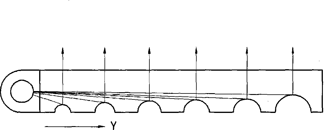
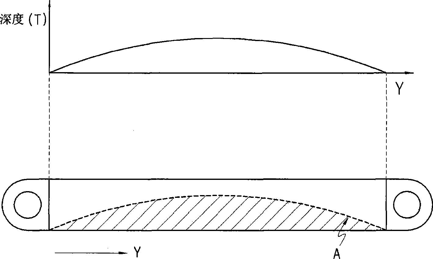
[0045] Figure 2a It is a sectional view of the backlight unit light guide plate provided with graphics of the present invention, Figure 2b yes means Figure 2a Diagram of the graphic depth profile in the light guide profile shown.

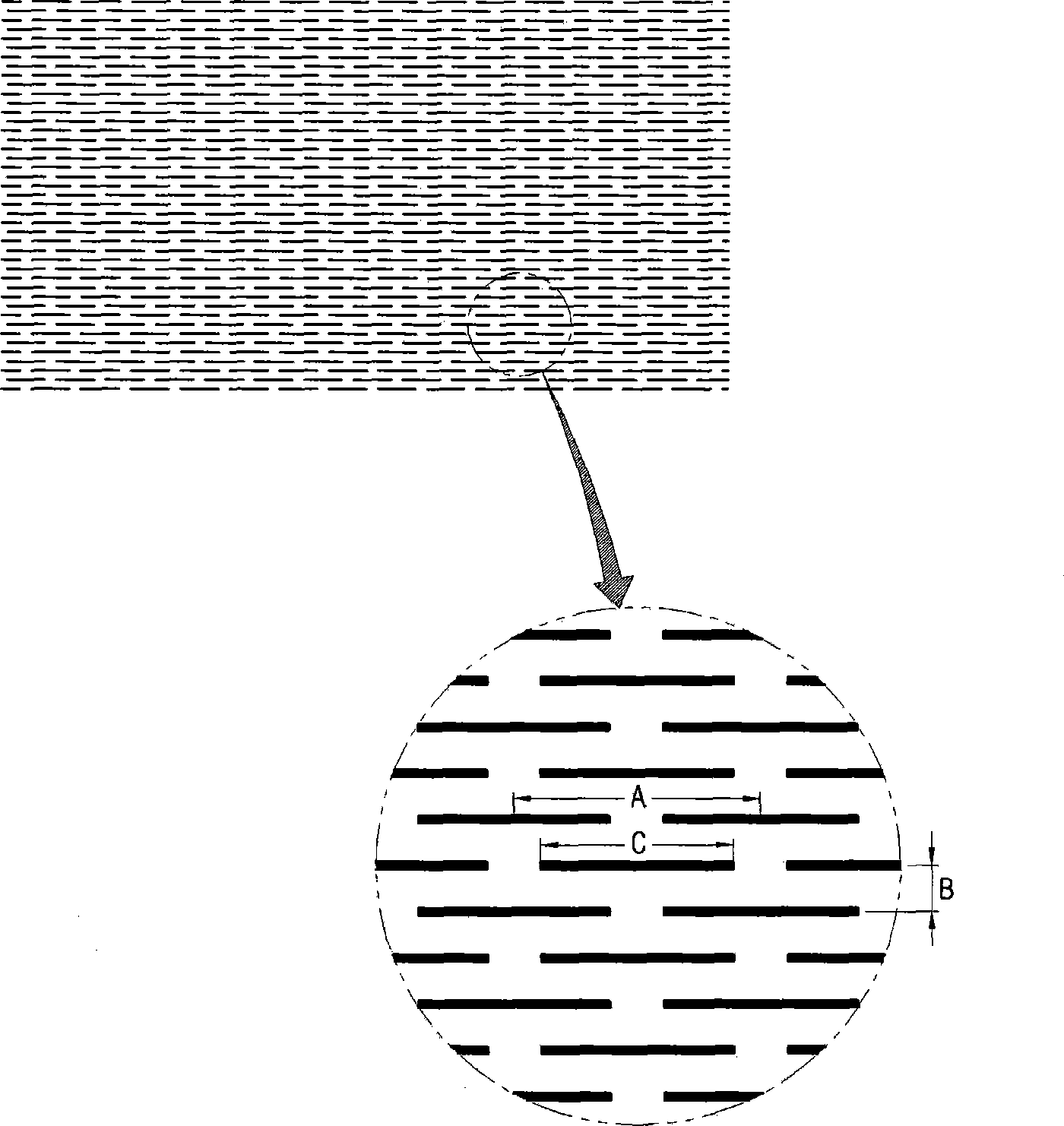
[0046] Such as Figure 2a As shown, the depth of the pattern formed by the patterning method of the light guide plate of the backlight unit provided with the pattern of the present invention has a contour line that changes as the distance from the light source, that is, the Y coordinate increases, so that the light emitted from the light source is reflected have the same brightness. In addition, the individual figures each have an engraved oval shape.

[0047] the above Figure 2a In , if the light source is set at both ends of the Y-axis of the light guide plate, such as F...


PUM


Abstract

The present invention relates to back light unit light guide plate composing picture on surface in laser picture composition mode, the picture composition mode can control the picture composition curved deep profile line. The invention concretely relates to a light guide plate of picture formed with the picture composition mode, according to the picture composition mode, deepness of the picture varies with distance to the light source when composing picture on the light guide plate, such that the reflection of light of light-in section is minimized in range of standard value, therefore the light source is transmitted to the back light section with minimized loss.

Description

technical field [0001] The present invention relates to a method of using a laser to form a curved pattern depth contour line on the surface of a light guide plate and a backlight unit light guide plate with a pattern formed by using the method, in particular to a light guide plate with a pattern formed by a patterning method, When the pattern is composed on one side of the light guide plate, the depth of the pattern away from the light source is deepened, so that the light reflection of the light incident part is minimized within the standard value, and the light source is transmitted to the backlight part with the minimum loss. Background technique [0002] In the field of flat panel display technology, liquid crystal displays, which are the most widely commercialized and practical, cannot emit light by themselves, so a light-emitting device called a backlight unit (Backlight unit) needs to be installed. The performance of liquid crystal displays not only depends on its own...

Claims


Application Information

Patent Timeline
IPC IPC(8): G02F1/13357G02B6/00G02F1/1335
CPCG02B5/021G02B6/0038G02B6/0051G02F1/133504G02F1/133602
Inventor 申景湜金相佑申英一
Owner 주비젼텍
Why Eureka
Try Eureka