Differential housing and production method

A differential device and casing technology, applied in the direction of differential transmission, transmission, control device, etc., can solve the problem of occupying space and achieve the effect of saving structural space

Inactive Publication Date: 2009-02-11
SONA BLW PRAZISIONSSCHMIEDE +1
View PDF0 Cites 0 Cited by
  • Summary
  • Abstract
  • Description
  • Claims
  • Application Information

AI Technical Summary

Problems solved by technology

In addition, the rivets need to take up space on both sides of the interconnected compon

Method used


Image

  • Differential housing and production method
  • Differential housing and production method
  • Differential housing and production method

Examples


Embodiment Construction

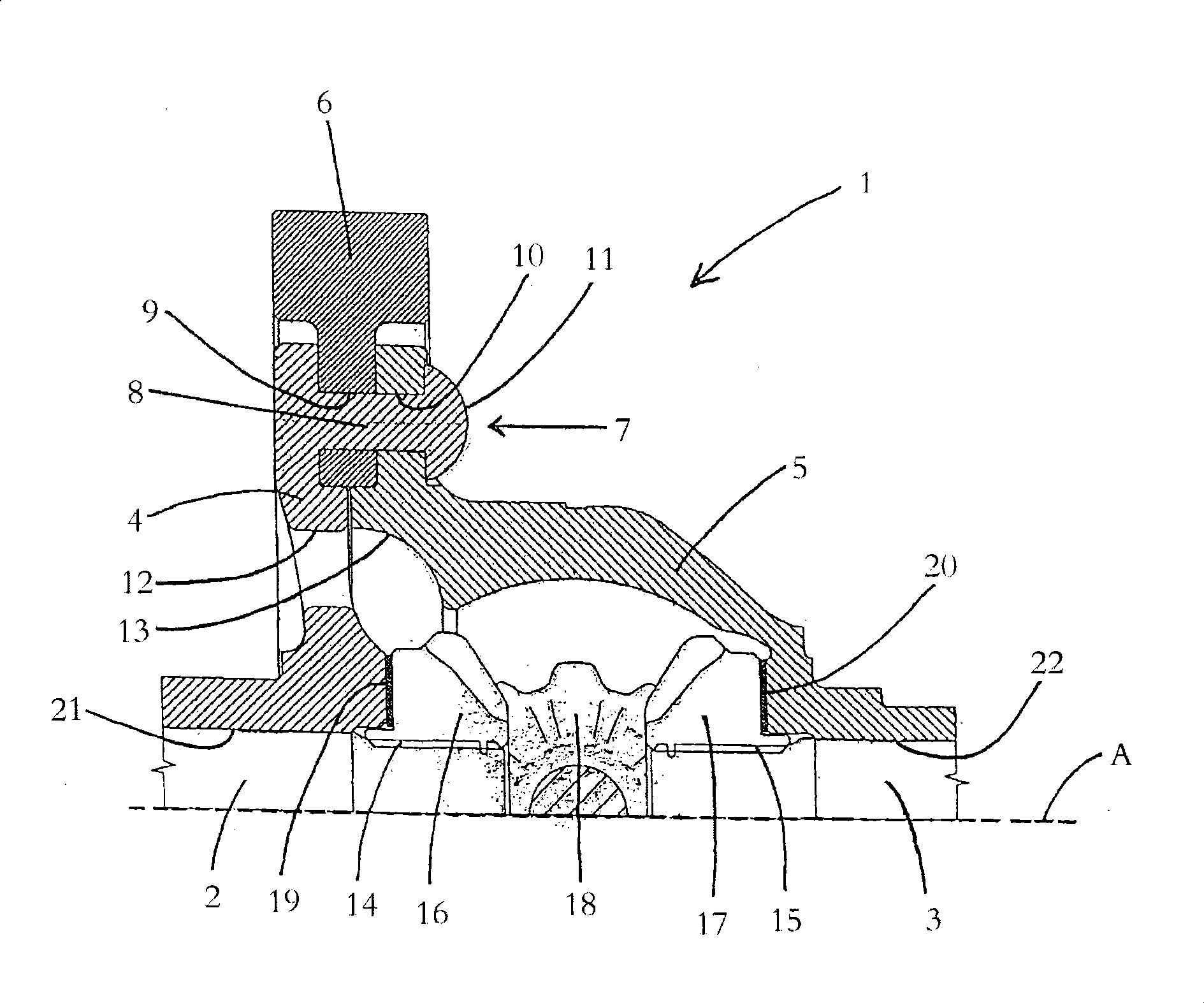
[0023] figure 1 Shows a half-sectional view of an embodiment of the housing 1 of the differential according to the invention, wherein the section plane extends through the axis A of the two coaxial driven shafts 2, 3 and thus through the center of the differential gear . The differential housing 1 comprises a housing cover 4 and a housing shell 5 , between which a drive gear 6 is clamped in a rotationally fixed manner by means of a riveted connection 7 . The riveted connection 7 is produced by means of a plurality of rivets distributed over the circumference of the housing and each integrally formed on the housing cover 4, figure 1 The sectional view of FIG. 1 shows only eight of the rivets 8 . The free end of the rivet 8 integrally formed on the housing cover 4 first passes through the bore hole 9 in the drive gear 6 and the bore hole 8 in the housing cover 5 before the free end of the rivet is deformed to establish the riveted connection 7, and at the same time the The co...


PUM


Abstract

Disclosed is a differential housing (1) comprising a housing bell (5) and a housing cover (4). The housing bell and the housing cover are connected to each other by means of a riveted joint (7) that is established by means of several rivets (8). The rivets of the riveted joint are monolithically molded onto the housing cover or the housing bell.

Description

technical field [0001] The invention relates to a housing of a differential device comprising a housing casing and a casing cover, wherein the casing casing and the casing cover are connected to each other by means of a riveted connection established by means of rivets, and to a method for manufacturing and assembling a differential method of the shell. Background technique [0002] The housing of the differential is used to accommodate and guide the components of the differential transmission, which generally consists of bevel and pinion gears making up the differential mechanism and a drive or ring gear driven by the drive. In addition, the housing of such a differential has openings on two opposite sides, preferably in the housing cover and the housing shell, for the output shaft protruding from the housing coaxially to different sides. According to the prior art, the housing cover and the housing shell of the housing of the final assembled differential are usually conne...

Claims


Application Information

Patent Timeline
IPC IPC(8): F16H57/02F16H48/08F16B5/04F16H48/38F16H48/40
CPCY10T74/2188F16H2048/385F16H48/40F16H48/08F16B5/045Y10T29/49943B60K17/16
Inventor 彼得·古特曼拉斯·沃克
Owner SONA BLW PRAZISIONSSCHMIEDE
Why Eureka
Try Eureka