Clamping structure for fastening motion self-compensation

A technology of automatic compensation and clamping, which is applied in the direction of clamping, manufacturing tools, supports, etc., can solve problems such as clamping is not tight, and achieve the effect of convenient maintenance and reduced wear

Inactive Publication Date: 2009-02-18
CHERY AUTOMOBILE CO LTD
View PDF2 Cites 32 Cited by
  • Summary
  • Abstract
  • Description
  • Claims
  • Application Information

AI Technical Summary

Problems solved by technology

[0009] The problem to be solved by the present invention is to provide a fixture structure with automatic clamping compensation. compensation

Method used


Image

  • Clamping structure for fastening motion self-compensation
  • Clamping structure for fastening motion self-compensation
  • Clamping structure for fastening motion self-compensation

Examples


Embodiment 1

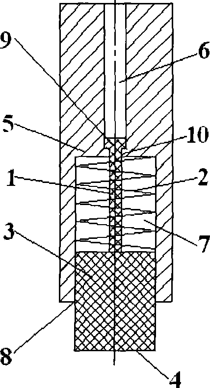
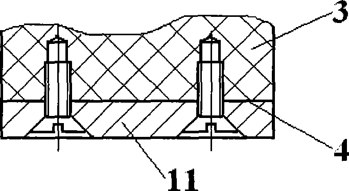
[0035] A clamping sleeve 5 is provided on the clamp structure, and one end thereof is provided with a clamping block installation counterbore 8, and the clamping block 3 is set in the clamping block installation counterbore 8, and the sides of the clamping block 3 and The inner wall of the clamping block mounting counterbore 8 forms a tight fit, and the clamping surface 4 is higher than the port of the clamping block mounting counterbore 8 .

Embodiment 2

[0038] A closed clamping air chamber 7 is formed between the bottom surface of the clamping block installation counterbore 8 and the end surface of the clamping block 3 inside the clamping block installation counterbore 8 .

[0039] The clamping air chamber 7 is provided, and the compressibility of the air is used to better realize the effect of increasing the elastic force.

Embodiment 3

[0041] A spring 2 is provided in the clamping air chamber 7, and the spring 2 is a compression spring, and the direction of expansion is to make the clamping block 3 move toward the outside of the clamping block mounting counterbore 8, and a spring is provided to limit it. The limit structure 9 of the clamping block moves outward to the maximum position, and this position makes the spring 2 have a pre-compression amount in the state of not clamping the workpiece.

[0042] The effect of setting the compression spring is the same as that of the second embodiment, and also solves the problem of possible air leakage in the second embodiment, because when the spring 2 is not clamped, it can make the capacity of the clamping air chamber 7 The cavity is enlarged to compensate for the gas. However, since the spring 2 is provided, there will inevitably be a problem of pushing the clamping block 3 out of the clamping sleeve 5. Therefore, a clamping block limiting structure 9 must be pro...


PUM


Abstract

The invention discloses a clamp structure for clamping and autocompensation; a clamping block (3) is arranged on a clamp; the surface of the clamping block (3) for clamping a workpiece is a clamping surface (4); and the clamping block (3) is made of an elastic material. With the technical proposal adopted, abrasion occurring in a clamping part and the change of the surface of the clamped workpiece are subjected to compensation by a simple elastic structure so as to ensure that a gripping jaw has enough clamping force in clamping and to guarantee the dimension of the workpiece after various machining processes (such as welding).

Description

technical field [0001] The invention belongs to the technical field of mechanical processing equipment, and relates to a clamping and positioning device for workpieces. More specifically, the invention relates to a clamping structure with automatic clamping compensation. Background technique [0002] In industrial production, especially in machinery manufacturing industrial production, various fixtures are widely used to clamp and position the workpiece to be processed. For example, in the automobile manufacturing industry, the quality control of the body-in-white involves welding strength and welding size. Among them, the welding size is mainly guaranteed by the clamping and positioning of the welding fixture, and the six degrees of freedom are limited by positioning and clamping. Stabilize the relative position between panels. When any problem occurs in clamping and positioning, under-positioning will occur, which may lead to changes in the welding size of the car body an...

Claims


Application Information

Patent Timeline
Patent Type & Authority Applications(China)
IPC IPC(8): B23Q3/06B23K37/053
Inventor 杨军
Owner CHERY AUTOMOBILE CO LTD
Why Eureka
Try Eureka