Cantilever beam external anchor stayed-cable bridge

A technology for cable-stayed bridges and suspension beams, applied in the direction of cable-stayed bridges, bridges, bridge parts, etc., can solve the problems of unfavorable long-term development and utilization of river hydraulic power, increased investment costs of bridge construction materials, difficulty in selection and construction operations, etc., to achieve Conducive to long-term development and utilization, saving bridge construction materials, reducing materials and weight

Inactive Publication Date: 2009-02-18
汪金来
View PDF0 Cites 4 Cited by
  • Summary
  • Abstract
  • Description
  • Claims
  • Application Information

AI Technical Summary

Problems solved by technology

Although self-anchoring can be realized, although the two components of the horizontal left and horizontal rightward forces of the tension acting on the cable tower on both sides of the cable tower cancel each other out, the load borne by the cable tower is mainly the main beam. The horizontal force is borne by the main girder. The main girder is not only supported on the pier but also on the stay cables. As the unit main girder is farther away from the cable tower, the horizontal component of the pull force of the stay cables is greater. The tower not only has to bear the weight of the main girder and the weight of the passing load, but also bears the huge horizontal component of the stay cable acting on the main girder. In order to increase the span and improve the strength, it is necessary to increase the thickness of the main girder and the The thickness of the cable towers and the number of cables lead to an increase in the cost of bridge construction materials; secondly, the main girder is restricted from being too far away from the cable towers, which limits the span and height between the two cable towers. Difficulties in design, selection of tower foundation positions and construction operations bring disadvantages to the long-term development and utilization of river hydraulics; in addition, when the main girder of a unit is seriously damaged due to unexpected accidents, it is difficult to replace the main girder

Method used


Image

  • Cantilever beam external anchor stayed-cable bridge

Examples


Embodiment Construction

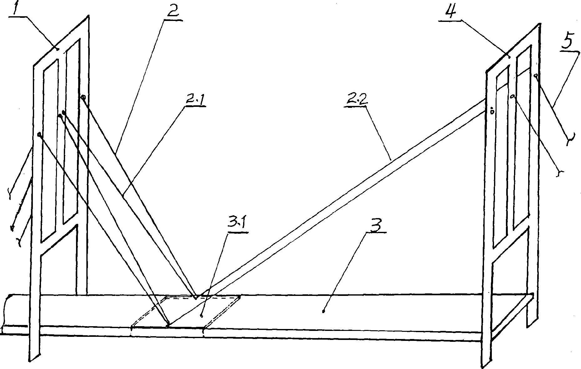
[0010] The specific structure of the suspension beam external anchor cable-stayed bridge of the present invention is further described in conjunction with the accompanying drawings and embodiments, and its features and advantages are more clear.

[0011] Embodiment 1 of the suspension beam external anchor cable-stayed bridge of the present invention, see figure 1 , its structure includes: cable tower 1, stay cable 2, main beam 3, each middle cable tower 1 is connected to main beam 3 on both sides through stay cable 2 on both sides, and each unit main beam 3.1 is respectively connected to the adjacent Stay cables are involved between the two pair of cable towers 1 and 4, and outer anchor cables 5 are set on the outermost two pair of cable towers 4 for connecting with ground anchor piles (not shown) at the bridge head.

[0012] Embodiment 2 of the suspension beam external anchor cable-stayed bridge of the present invention, see figure 1 , its structure includes: in the structur...


PUM


Abstract

The invention belongs to cable-stayed bridge field and relates to a cable-stayed bridge with the suspended girders externally anchored. The cable-stayed bridge is mainly characterized in that at least three stay cables are connected between each side of each unit girder and two adjacent cable towers; external anchorage cables are arranged on the two outmost cable towers. Compared with the current anchorage and connection mode of the cable-stayed bridge, the invention enables the girders to be stably suspended and pulled in the air, and interaction force among the unit girders is greatly weakened. The cable-stayed bridge can make use of the strength of the components thereof, thereby not only reducing material consumption and weight of the components like the girders but also increasing the span and height between the cable towers, which is good for choosing the bases for the cable towers according to landform and geology and good for developing navigation capacity.

Description

technical field [0001] The invention belongs to the field of buildings, and relates to a cable-stayed bridge, in particular to a suspension-beam external-anchored cable-stayed bridge. Background technique [0002] A cable-stayed bridge is an important structural form of modern long-span bridges, including cable towers, cable-stayed cables, main girders, and piers. Many beams disperse the force of the stay cables from the main girder, and the main girder on each side is pulled by the stay cables from a pylon. Although self-anchoring can be realized, although the two components of the horizontal left and horizontal rightward forces of the tension acting on the cable tower on both sides of the cable tower cancel each other out, the load borne by the cable tower is mainly the main beam. The horizontal force is borne by the main girder. The main girder is not only supported on the pier but also on the stay cables. As the unit main girder is farther away from the cable tower, the...

Claims


Application Information

Patent Timeline
Patent Type & Authority Applications(China)
IPC IPC(8): E01D11/04E01D19/14
Inventor 汪金来
Owner 汪金来
Why Eureka
Try Eureka