
Design method of two phase flow pump impeller

A design method and technology for pump impellers, which are applied to the components of pumping devices for elastic fluids, pumps and pumps for special fluids, etc. Uniform variation, small hydraulic and frictional losses, and extended service life

Inactive Publication Date: 2009-02-18
许洪元
View PDF0 Cites 24 Cited by
  • Summary
  • Abstract
  • Description
  • Claims
  • Application Information

AI Technical Summary

Problems solved by technology

[0003] 1. Most of the pumps are centrifugal pumps with medium and low specific speed. In order to simplify the design and manufacture of the impeller, the impeller blades usually adopt cylindrical blades, that is, the blades are perpendicular to the cover plates on the front and rear sides of the impeller. Although the manufacture is relatively simple, the hydraulic loss is relatively high. large twisted blade
[0004] 2. In order to reduce the pressure before the mechanical seal or packing seal to reduce the sand wear on the sealing surface and reduce the leakage of the pump, the geometric parameters of the auxiliary blades, auxiliary impellers and other dynamic sealing components such as the number of blades, height, diameter and blade It is difficult to achieve the optimization of geometric parameter design through empirical improvement.

Method used


Image

  • Design method of two phase flow pump impeller
  • Design method of two phase flow pump impeller

Examples


Embodiment Construction

[0016] In order to make the purpose, technical solutions and advantages of the present invention clearer, the implementation of the present invention will be further described in detail below in conjunction with the accompanying drawings:

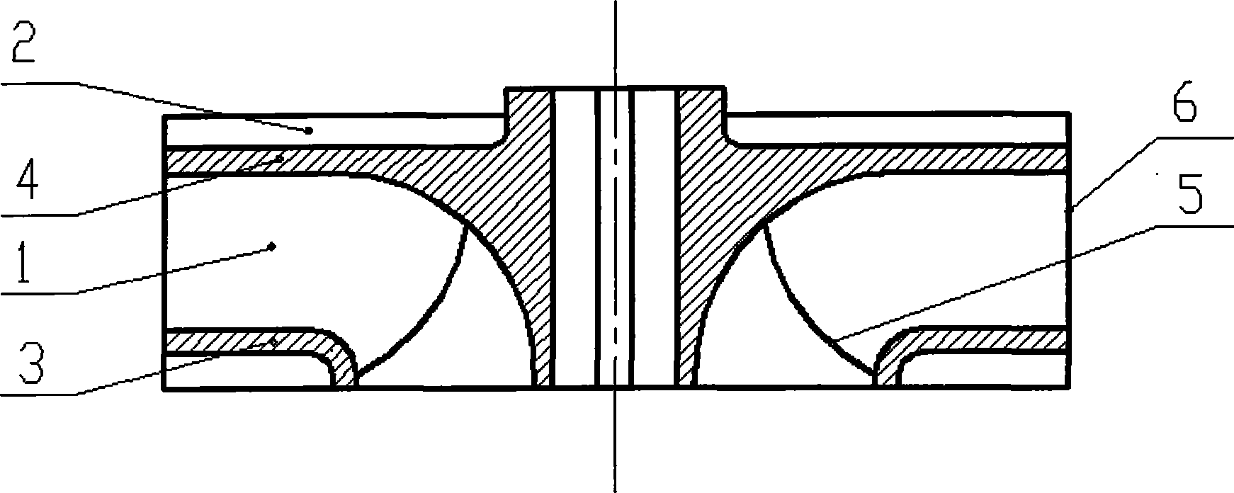
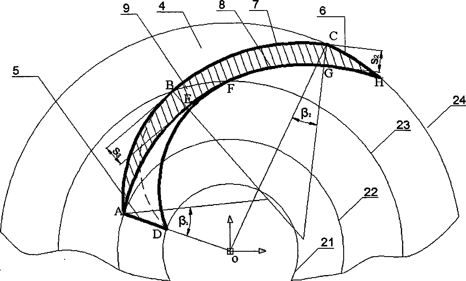
[0017] like figure 1 As shown, the impeller shaft surface structure of the present invention is shown, which mainly includes: impeller main blade 1, impeller auxiliary blade 2, impeller front cover plate 3, impeller rear cover plate 4, impeller inlet side 5 and impeller outlet side 6, The impeller main blade 1 is inclined from the blade inlet edge 5 to the impeller front cover plate 3 and the impeller rear cover plate 4, and the inclined shape transitions to be perpendicular to the front and rear cover plates, forming a semi-twist that the outlet section is perpendicular to the two side cover plates blade. The profile of the main blade 1 of the impeller adopts an arc shape, usually 2-3 segments of arcs. It also includes: firstly determine...


PUM


Abstract

The invention discloses the design method of a two-phase flow pump; the two-phase flow pump comprises a slurry pump, a mud pump, a diving slurry pump, a diving mud pump and a diving two-phase pump; the impeller includes a main impeller and an auxiliary impeller; the main impeller mainly comprises a main vane, an auxiliary vane, a front cover plate and a back cover plate; the impeller is mainly arranged on an impeller shaft; the main vane is inclined to the front cover plate and the back cover plate through the vane inlet segment; the vane outlet segment is vertical to the front cover plate and the back cover plate to form a semi-twisted vane; the vane contour line on the impeller front cover plate has smooth transition to the vane contour line on the impeller back cover plate to form the surface of the semi-twisted vane. The auxiliary vane of the impeller and the auxiliary impeller construct a dynamic sealing device. Based on the semi-twisted vane in the invention, the water power loss and the friction loss are smaller than that of the cylindrical vane; the vibration and noise of the pump are reduced; the pump efficiency is improved; the service life of the impeller is prolonged; meanwhile, the operation of the pump become more stable.

Description

technical field [0001] The invention relates to a two-phase flow pump, in particular to a design method for the impeller of the two-phase flow pump. Background technique [0002] Existing two-phase flow pumps (including submersible two-phase flow pumps) have disadvantages such as low efficiency, easy leakage at shaft seals, and easy damage to bearings when pumping solid-liquid mixtures such as slag and mud, which affect the safety and reliability of pump operation . Although some two-phase flow pumps have made some improvements in design, there are still the following deficiencies: [0003] 1. Most of the pumps are centrifugal pumps with medium and low specific speed. In order to simplify the design and manufacture of the impeller, the impeller blades usually adopt cylindrical blades, that is, the blades are perpendicular to the cover plates on the front and rear sides of the impeller. Although the manufacture is relatively simple, the hydraulic loss is relatively high. Th...

Claims


Application Information

Patent Timeline
IPC IPC(8): F04D29/24F04D29/22F04D29/08F04D7/04
Inventor 许洪元
Owner 许洪元
Learn More