Reflection surface system capable of spacing expansion

A reflective surface and space technology, applied in the field of aerospace, can solve the problems of difficult application of large-scale deployable devices, difficulty in ensuring surface accuracy, and low surface accuracy, and achieve the goals of reducing quality, high configuration accuracy, and improving configuration accuracy Effect

Inactive Publication Date: 2012-07-04
XIDIAN UNIV
View PDF1 Cites 8 Cited by
  • Summary
  • Abstract
  • Description
  • Claims
  • Application Information

AI Technical Summary

Problems solved by technology

This structural scheme has two major defects: one is that its radial and height directions are not high in capacity, and it is difficult to apply it to large-scale expandable devices; Truss, surface accuracy is difficult to guarantee
This structural scheme also has two major defects: one is that the overall inflatable structure, due to its huge inflated volume, has a not low surface density, even higher than the excellent mesh-shaped deployable reflector antenna; the other is that its shape The surface accuracy is generally inferior to the mesh deployable reflector antenna

Method used


Image

  • Reflection surface system capable of spacing expansion
  • Reflection surface system capable of spacing expansion
  • Reflection surface system capable of spacing expansion

Examples


example 1

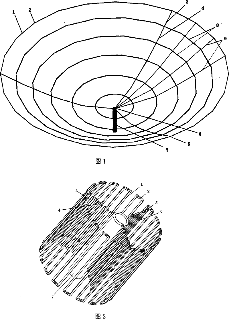
[0061] Example 1, developing a hemispherical reflector system with a diameter of 16m

[0062] The collapsed state of the device is as figure 2 As shown, the expanded state is as figure 1 shown.

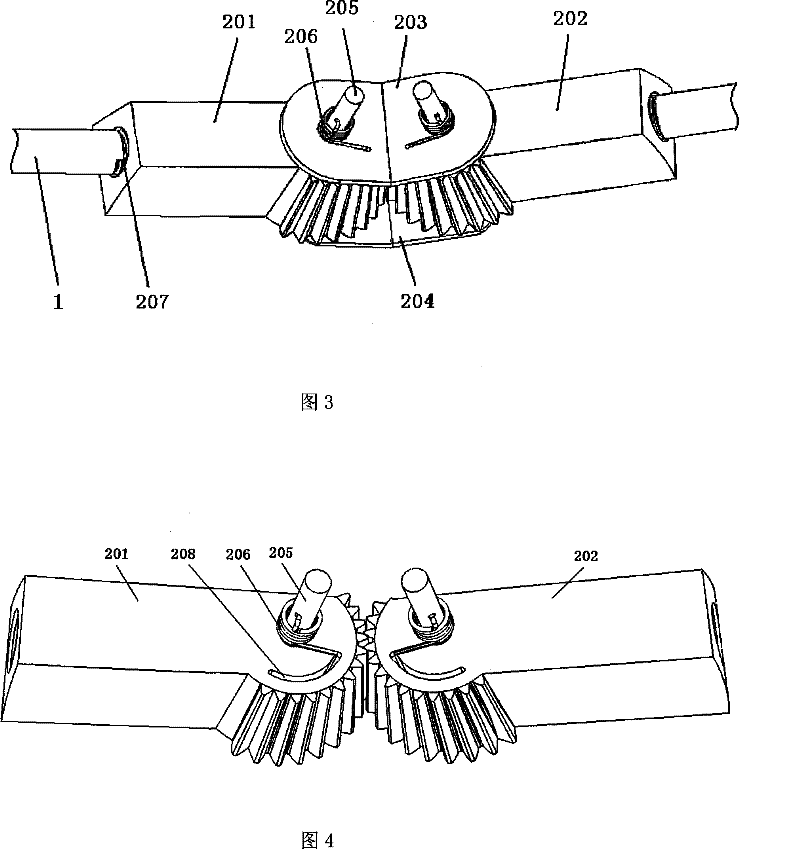
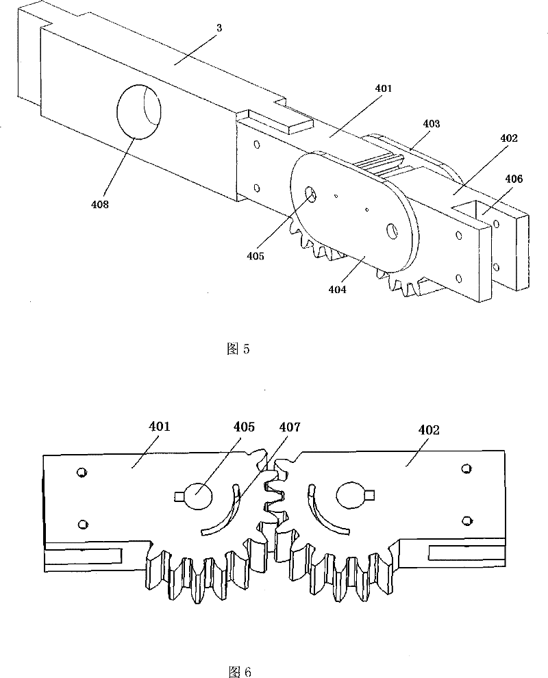
[0063] There are 36 ring rods on the caliber ring structure, and a total of 24 rib rods on the radial three supporting rib structures. Both the ring bar and the rib bar are straight single bars with a rectangular hollow section with an outer dimension of 0.025m×0.020m and an inner dimension of 0.020m×0.016m. The ring rod connection joint adopts image 3 The two-part bevel synchronous gear mechanism driven by the torsion spring shown in . The connection angle of the two synchronous mechanisms is 170 degrees. The rib-rod connection joint adopts Figure 5 Two cylindrical synchronous gear mechanisms driven by torsion springs shown in . The ring bar and the rib bar adopt the Figure 5 The groove structure shown in the figure is respectively assembled with the ring-rod connecting j...

example 2

[0065] Example 2, deploying a rotating parabolic system with a diameter of 60m.

[0066] The collapsed state of the device is as Figure 13 shown.

[0067] There are 96 ring rods on the caliber ring structure, and a total of 120 rib rods on the six radial support rib structures. The ring rod adopts an arc single rod with a circular tube section with an outer diameter of 0.03m and an inner diameter of 0.02m; the rib rod adopts a hollow structure straight single rod with a rectangular solid cross section of 0.03m×0.02m. The focal diameter ratio of a paraboloid is 0.5. The ring rod connection joint adopts image 3 The two conical synchronous gear mechanisms driven by the torsion spring shown in , the connection angle of the two synchronous mechanisms is 176.25 degrees, and the ring rod adopts image 3 The sleeve structure shown in the threaded assembly with the ring rod connection joint. The rib-rod connection joint adopts Figure 5 The two cylindrical synchronous gear mech...

example 3

[0069] Example 3, develop a rotating paraboloid system with a diameter of 6m.

[0070] The unfolded state of the device is as Figure 18 shown.

[0071] There are 12 ring rods on the caliber ring structure, and a total of 24 rib rods on the six radial support rib structures. Both the ring bar and the rib bar are straight single bars with a rectangular solid cross-section with a size of 0.008m×0.006m. The focal diameter ratio of a paraboloid is 0.3. The ring rod connection joint adopts image 3 The two conical synchronous gear mechanisms driven by the torsion spring shown in , the connection angle of the two synchronous mechanisms is 150 degrees. The rib-rod connection joint adopts Figure 5 Two cylindrical synchronous gear mechanisms driven by torsion springs shown in . The ring bar and the rib bar adopt the Figure 5 The groove structure shown in the figure is respectively assembled with the ring-rod connecting joint and the rib-rod connecting joint. The central cylin...


PUM


Abstract

The invention discloses a reflective surface system which can unfold the space, comprising a foldable ring rod, a foldable rib rod, a connecting joint, a central cylinder, and an air aerated circular ring and a driving rope. The foldable ring rod (1) and the foldable rib rod (3) are respectively connected to the ring rod connecting joint (2) and the rib rod connecting joint (4), forming a ring-rib structure; the ring-rib structure is connected to the central cylinder (7) via a ring rib connecting joint (5) and a rib cylinder connecting joint (6); the air aerated circular ring (8) and the driving rope (9) are provided on the grid skeleton in crossing way to form the reflective surface structure. The air aerated circular ring can be solidified after the molding to enhance the structure precision of the reflective surface; the driving rope can enhance the structure precision of the reflective surface; the metal net or the aluminum plating film structure bound to the driving rope eventually form the expected large foldable reflective surface. The invention is used for forming a large foldable device of the foldable antenna, the reflector or gathers.

Description

technical field [0001] The invention belongs to the field of aerospace technology, in particular to a novel deployable reflective surface system. It is mainly used in space-borne large-scale deployable antennas, space-borne large-scale deployable reflectors or concentrators in the aerospace field, and can also be applied to large-scale mobile antennas, large-scale mobile reflectors or concentrators on the ground. Background technique [0002] Large reflectors or concentrators have the functions of collecting and focusing electromagnetic waves or solar energy, and have been widely used in many fields. With the continuous development of aerospace technology and the continuous expansion of aerospace applications, space large-scale deployable devices such as deployable antennas and solar panels have been more and more widely used, and even become one of the key components for the success of satellite launches. However, the limitations of launch vehicle size and carrying capacit...

Claims


Application Information

Patent Timeline
Patent Type & Authority Patents(China)
IPC IPC(8): H01Q15/14
CPCF16C11/04
Inventor 郑飞陈梅李苇
Owner XIDIAN UNIV
Why Eureka
Try Eureka