
Passenger car braking beam sleeve-retreating and sleeve-insetting machine

A brake beam and back sleeve technology, which is applied in the direction of manufacturing tools, milling machine equipment details, milling machine equipment, etc., can solve problems affecting driving safety, brake beam cracks, and low work efficiency, so as to ensure the quality of car repair and work smoothly , reliable effect

Inactive Publication Date: 2009-02-25
大连山元机械制造有限公司
View PDF0 Cites 0 Cited by
  • Summary
  • Abstract
  • Description
  • Claims
  • Application Information

AI Technical Summary

Problems solved by technology

[0002] At present, there are pin sleeves in the pin holes used to hang various auxiliary parts on the national railway passenger car bogies. When the bogie is in use after a section repair or factory repair period, the old pin sleeves must be removed. At the same time, install a new pin sleeve with a suitable size in the original pin hole. Since the size of the two end sleeves of the brake beam in the bogie is Φ55mm, the length is 65mm, and the skin thickness is 5mm, the work of retreating and inserting the sleeve is extremely troublesome. The traditional method of withdrawing and inserting the sleeve is to remove and install the old sleeve manually by smashing it with a sledgehammer or cutting it with acetylene, which will easily cause cracks in the brake beam and seriously affect the driving safety. It is very troublesome for workers to operate, low work efficiency and high cost. It is very necessary to develop a new type of device for withdrawing and inserting sleeves to overcome the existing problems in the existing technology.

Method used


Image

  • Passenger car braking beam sleeve-retreating and sleeve-insetting machine
  • Passenger car braking beam sleeve-retreating and sleeve-insetting machine
  • Passenger car braking beam sleeve-retreating and sleeve-insetting machine

Examples


Embodiment Construction

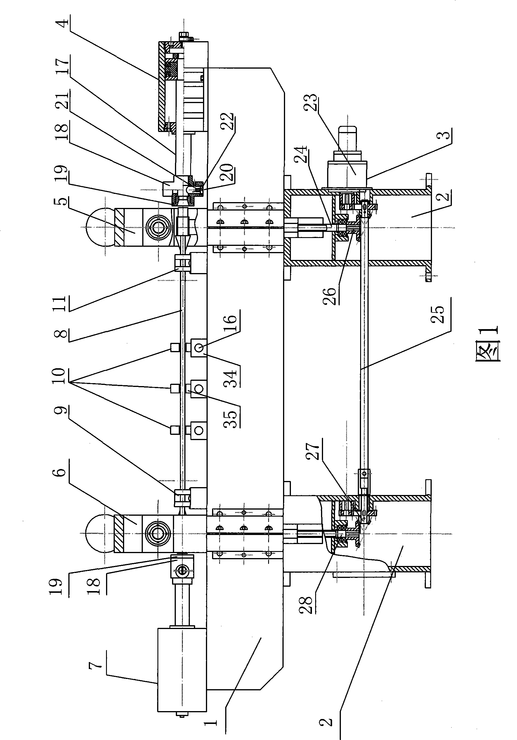
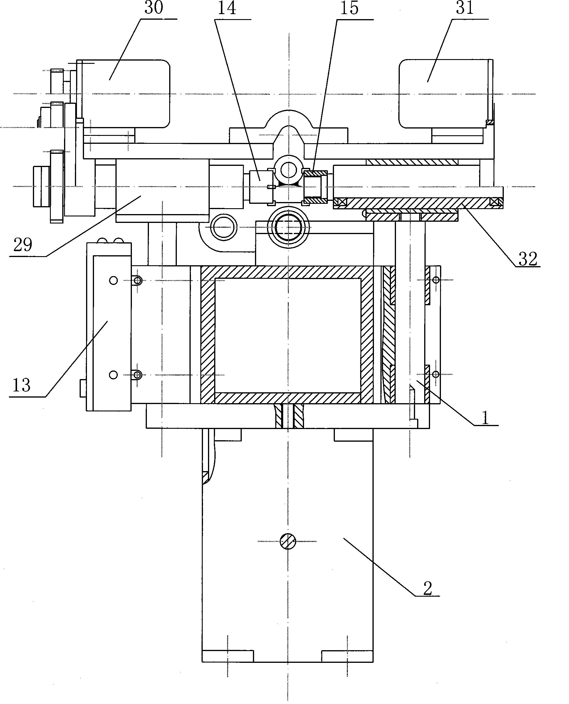
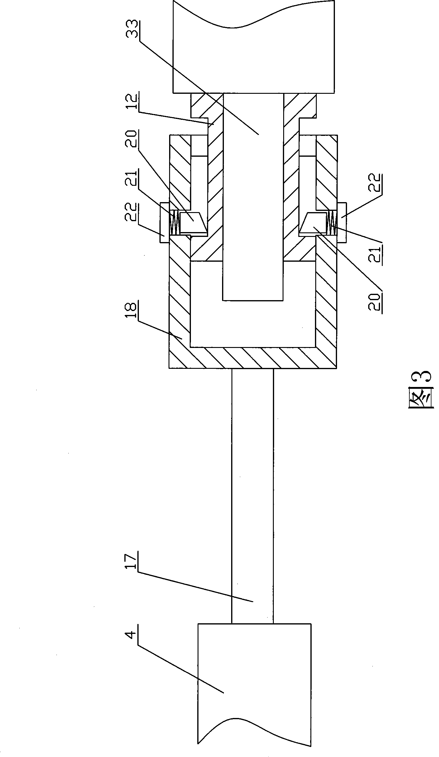
[0021] The specific embodiment of the present invention is as shown in the accompanying drawings; Two supports 2 are housed below the body 1, and a transmission pair is housed in the support 2, and a motor 23 drives the bevel gear pair 26, 27 to make the transmission shaft 24 , 28 rotate and then drive left and right milling cutter holders 29,32 to rise or fall; Left and right milling cutter heads 14,15 are housed on left and right milling cutter holders 29,32. Drive left and right milling head 14,15 rotary cuttings by motor 30,31. Left and right hydraulic cylinders 7, 4 and left and right milling devices 6, 5 are installed on the left and right sides of the working platform of the body 1 respectively. Fixed molds 9, 11 and three clip pushers 10 are respectively housed in the middle of the workbench. When the sleeve is withdrawn, the movable pin 20 in the push head 18 is pressed in by the milled sleeve 12 and the milled sleeve 12 enters the cavity of the push head 18. At this...


PUM


Abstract

The invention belongs to a special device used for the automatic tapering and automatic embedding of shaft sleeves at two ends of a brake beam in railway passenger car, in particular to a sleeve removing and sleeve embedding machine used for the brake beam of passenger car; the structure of the machine consists of a hydraulic station, an operation control device and an embedding removing device; the embedding removing device consists of a machine body with a supporter, a lifting transmission device, a left hydraulic cylinder and a right hydraulic cylinder, a left milling device, a right milling device and a positioning clamping device; the lifting transmission device drives the left milling device and the right milling device to ascend or descend; the left milling device and the right milling device are respectively provided with two milling heads; left end and right end of the working platform of the machine body are respectively provided with the left hydraulic cylinder and the right hydraulic cylinder; a left fixed positioner, a right fixed positioner and a group of movable push-clamps are respectively arranged between the left milling device and the right device; the machine has the advantages of strong pertinence, convenient usage, simple operation, novel structure and reliable operation.

Description

technical field [0001] The invention belongs to the special equipment for automatic withdrawing and automatic mounting of the two-end axle sleeves of the brake beam in the railway passenger car. Background technique [0002] At present, there are pin sleeves in the pin holes used to hang various auxiliary parts on the national railway passenger car bogies. When the bogie is in use after a section repair or factory repair period, the old pin sleeves must be removed. At the same time, install a new pin sleeve with a suitable size in the original pin hole. Since the size of the two end sleeves of the brake beam in the bogie is Φ55mm, the length is 65mm, and the skin thickness is 5mm, the work of retreating and inserting the sleeve is extremely troublesome. The traditional method of withdrawing and inserting the sleeve is to remove and install the old sleeve manually by smashing it with a sledgehammer or cutting it with acetylene, which will easily cause cracks in the brake beam...

Claims


Application Information

Patent Timeline
Patent Type & Authority Applications(China)
IPC IPC(8): B23P19/027B23C3/00
Inventor 孙楷王国长孙淑君
Owner 大连山元机械制造有限公司
Learn More