Cardboard box structure

A box structure, carton technology, used in rigid containers, containers, packaging and other directions

Inactive Publication Date: 2009-02-25
QUANTA COMPUTER INC
View PDF0 Cites 7 Cited by
  • Summary
  • Abstract
  • Description
  • Claims
  • Application Information

AI Technical Summary

Problems solved by technology

[0003] However, in the above box structure, at least one place must be assembled by sticking or nailing. Therefore, in addition to the material of the box itself, materials such as glue and needles must also be prepared, which becomes the cost of expenditure.
In addition, handles, cushioning materials, etc. are usually made of plastic and other materials. Although they can be recycled and reused, if they cannot be reused, the disposal of these parts will become an environmental protection issue.

Method used


Image

  • Cardboard box structure
  • Cardboard box structure
  • Cardboard box structure

Examples


Embodiment Construction

[0039] The following will clearly illustrate the spirit of the present invention with the accompanying drawings and detailed descriptions. After those skilled in the art understand the preferred embodiments of the present invention, they can be changed and modified by the technology taught by the present invention without departing from the present invention. The spirit and scope of the invention.

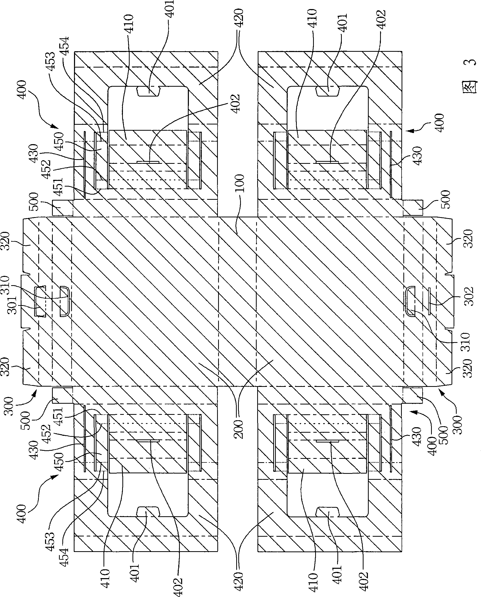
[0040] Fig. 3 shows the unfolded view of the sheet material of the carton structure of the present invention, the line segment shown in the figure is the mountain line folding (the sheet material on both sides of this line segment is folded toward the depth direction of the drawing, so that this line segment Protrusion), the ------ line segment shown in the figure is valley line folding (fold the sheet material on both sides of this line segment toward the floating direction of the drawing to make this line segment concave), as shown in the figure. ...The line segment can be folded...


PUM


Abstract

A carton structure which is formed by folding a sheet includes a bottom sheet and two side sheets which are connected to the two sides of the bottom sheet respectively. The two side sheets respectively comprise a top sheet which is connected to the side of the side sheet which is opposite to the bottom sheet and two case structure folding sheets of two margins which are connected to the side sheet but are not connected to the bottom sheet and the top sheet. The two case structure folding sheets comprise a frame sheet, a buffer folding sheet and at least a folding sheet for adjustment respectively. The central part of the frame sheet forms an opening which can form a U-shaped buffer space together with the top sheet, the lateral margin of the side sheet and the bottom sheet after being folded. The buffer folding sheet is connected to one side of the frame sheet which is close to the side sheet and forms a step-shaped buffer structure after being folded. The folding sheet for adjustment is formed along two opposite sides of the opening of the frame sheet and is folded to form a buffer space or a containing space according to the size of the containing space needed.

Description

technical field [0001] The invention relates to a carton structure. Background technique [0002] Such as figure 1 As shown, in a conventional carton, side panels 200', connecting tongues 210', and multiple wing panels 300' are formed on a cardboard, and then the side panels 200' are connected to the connecting tongues 210' by pasting or nailing. Form a tube shape, and then use a plurality of wing plates 300 ′ to close open ports on both sides of the tube shape formed around the side plate 200 ′ by sticking or nailing. In addition, if figure 2 The shown box structure including the handle part forms two through holes 301' and a support structure 302' respectively above the box body relative to the wing plate, and a handle part 400' is set in the two through holes 301', and the bottom of the box body The wing plates 103' are designed to be interfittable, and can close the open port at the bottom of the tube formed by the side plates 201' without sticking or nailing. Furth...

Claims


Application Information

Patent Timeline
Patent Type & Authority Applications(China)
IPC IPC(8): B65D5/00B65D5/44B65D5/50
Inventor 梁予
Owner QUANTA COMPUTER INC
Why Eureka
Try Eureka