
System for switching laying bedding plane of signal line

A technology for switching systems and signal lines, applied in special data processing applications, instruments, electrical digital data processing, etc., can solve the problems of deleting and redrawing signal lines, increasing workload, unavoidable errors, and tedious and inconvenient processing. Achieve the effect of improving work efficiency and industrial interests, and making up for functional defects

Inactive Publication Date: 2010-06-16
INVENTEC CORP
View PDF4 Cites 0 Cited by
  • Summary
  • Abstract
  • Description
  • Claims
  • Application Information

AI Technical Summary

Problems solved by technology

It can be seen from this that the switching operation of many signal lines through the Allegro software will require repeated setting steps, so not only the processing is cumbersome and inconvenient, but also prone to errors
[0004] For this reason, the current general signal line switching method is to first delete the original circuit line manually, and then manually draw in the target circuit layer, and abandon the layer signal line switching function provided by Allegro software, but, as mentioned above , the speed of manual wiring is slow, and the operation of deleting and redrawing signal lines will greatly increase the workload, resulting in a decrease in efficiency; therefore, although manual work is more convenient than the interlayer function of signal lines in Allegro software, but in In the case of a large workload, it is difficult to avoid the occurrence of errors
[0005] Therefore, due to the inherent functional defects of the software, it is necessary to use manual line-changing operations to carry out repeated work. is an urgent problem to be solved

Method used


Image

  • System for switching laying bedding plane of signal line
  • System for switching laying bedding plane of signal line
  • System for switching laying bedding plane of signal line

Examples


Embodiment Construction

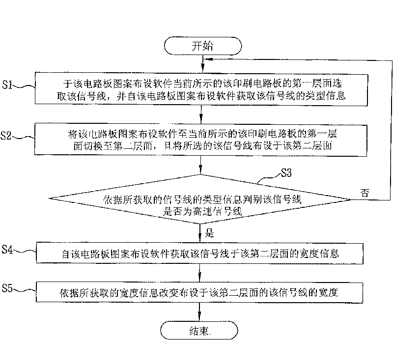
[0022] Embodiments of the present invention are described below through specific examples, and those skilled in the art can easily understand other advantages and effects of the present invention from the content disclosed in this specification. The present invention can also be implemented or applied through other different specific examples, and various modifications and changes can be made to the details in this specification based on different viewpoints and applications without departing from the spirit of the present invention.

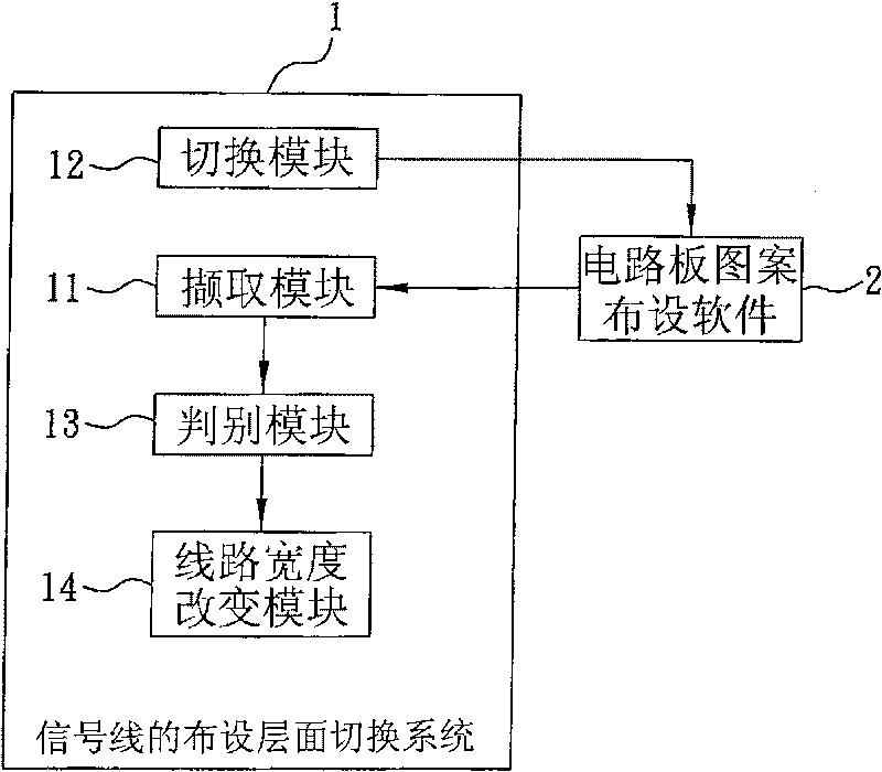
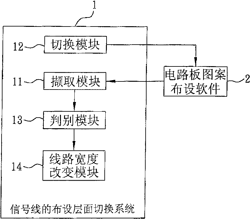
[0023] see figure 1 , is the layout layer switching system of the signal line of the present invention, is carried on the computer equipment that has the circuit board pattern layout software 2 of printed circuit board (PCB), in order to switch the signal line that is laid on the first layer of this printed circuit board Layout to the second level of the printed circuit board, wherein the circuit board pattern layout software 2 at least defines ...


PUM


Abstract

The invention provides a signal wire layout plane switch system, which is carried on a computer unit having printed circuit board circuit diagram layout software and is used for switching signal wireslaid out in the first plane of a printed circuit board onto the second plane of the printed circuit board. At least the type information of the signal wires to be laid out, and the width informationof the signal wires in the first plane and the second plane are defined in the circuit diagram layout software. The type information of the signal wires selected from the first plane of the printed circuit board currently displayed by the printed circuit board diagram layout software is acquired from the software so that when the printed circuit board diagram layout software is switched to the second plane from the first plane of the printed circuit board currently displayed, the selected signal wires are displayed on the second plane; the width of the signal wires laid out on the second planeis changed according to the width information of the signal wires on the second plane acquired by the circuit diagram layout software.

Description

technical field [0001] The present invention relates to a signal line layout level switching system, in particular to a signal line layout level switching system carried in a computer device with printed circuit board (PCB) circuit board pattern layout software. Background technique [0002] With the development of high-density integrated circuits, there is a need to use electronic design automation (Electronic Design Automation: EDA) software for wiring. At present, the more common wiring method is the combination of automatic wiring and manual wiring. The two wiring methods have their own characteristics. Compared with manual wiring, automatic wiring has the characteristics of fast completion speed and high accuracy, and can quickly respond to market demand for products. Design requirements, while manual wiring can make adjustments to partial wiring methods that do not meet the design, so as to improve the efficiency of wiring. [0003] Just because the function of the au...

Claims


Application Information

Patent Timeline
Patent Type & Authority Patents(China)
IPC IPC(8): G06F17/50
Inventor 魏亮杨淑敏
Owner INVENTEC CORP
Features
  • Generate Ideas
  • Intellectual Property
  • Life Sciences
  • Materials
  • Tech Scout
  • Unparalleled Data Quality
  • Higher Quality Content
  • 60% Fewer Hallucinations
Learn More