Temperature fuse

A technology of thermal fuses and fuses, applied in emergency protection devices, electrical components, circuits, etc.

Active Publication Date: 2009-02-25
UCHIHASHI ESTEC
View PDF2 Cites 2 Cited by
  • Summary
  • Abstract
  • Description
  • Claims
  • Application Information

AI Technical Summary

Problems solved by technology

[0010] Therefore, it is problematic to shorten the distance between the welded part of the fuse element on the above-mentioned membrane electrode and the joi...

Method used


Image

  • Temperature fuse
  • Temperature fuse
  • Temperature fuse

Examples


Embodiment Construction

[0031] Below, while referring to the attached Figure 1 Embodiments of the present invention will be described.

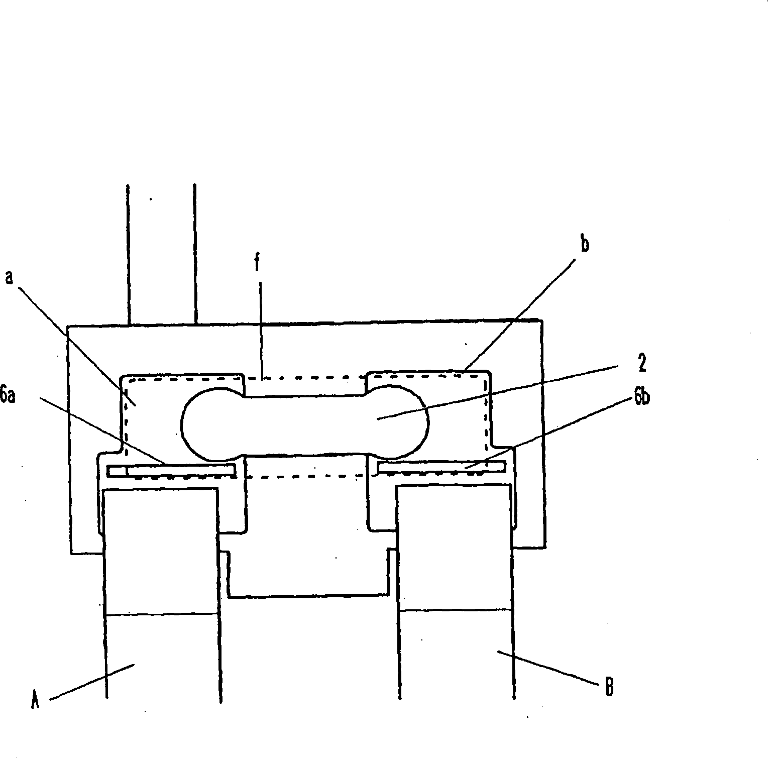
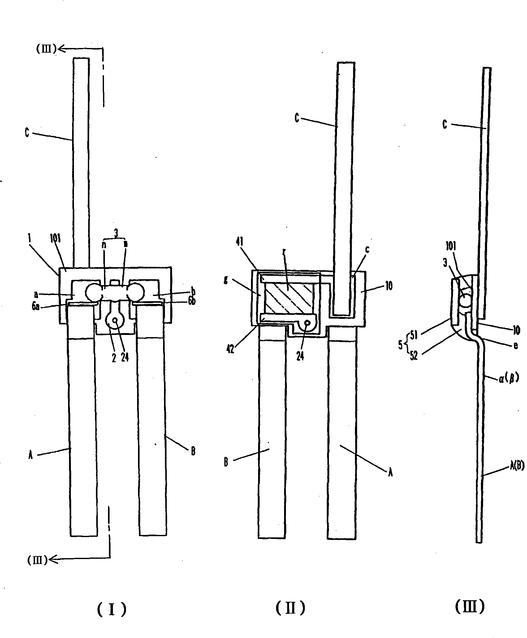
[0032] figure 1 It is a partially cutaway plan view showing an embodiment of the thermal fuse according to the present invention.

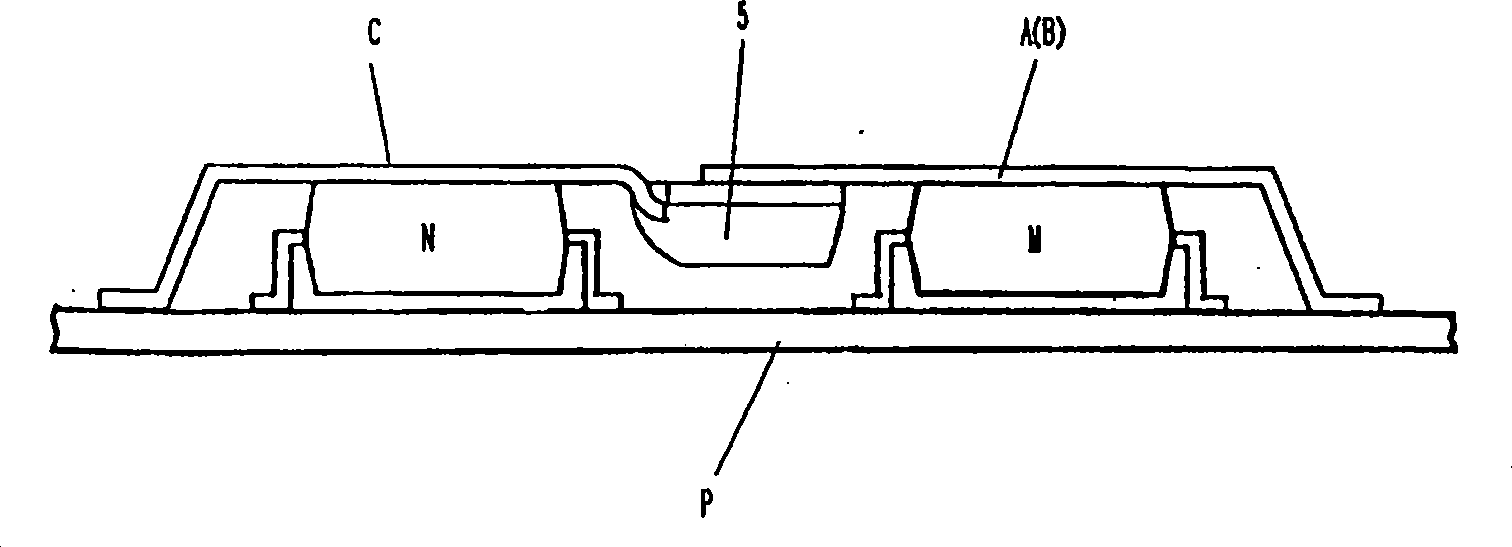
[0033] exist figure 1 Among them, 1 is an insulating substrate excellent in heat resistance and thermal conductivity, for example, a ceramic plate can be used. a and b are a pair of film electrodes for fuse element connection formed on one surface of the substrate, and can be provided by printing and firing a conductive paste such as silver paste. A and B are ribbon lead conductors, and the thickness of the ceramic plate 1 is as thin as 250 μm to 400 μm, and is soldered to the membrane electrode for fuse element connection. If welding, for example, spot welding lead conductors on an ultra-thin ceramic plate of 250 μm to 400 μm, there is concern about cracks and damage to the ceramic plate, but this disadvantage can be eliminated by...


PUM


Abstract

This invention provides a temperature fuse, in substrate based temperature fuses, shortening distance between welding position of fuse element on film electrode and joint part of lead conductor to achieve minimization of the main body. Thus, fuse elements (3) are thoroughly welded on the film electrodes (a, b), lead conductors (A, B) are combined with the film electrodes (a, b) via soft soldering process, meltdown solder for soft soldering process or immerged extending isolation barriers (6a, 6b) for fuse element welding process are disposed between the welding position on each of the film electrodes (a, b) and soft soldering joint of the lead conductors.

Description

technical field [0001] The invention relates to a temperature fuse, which can be used as a resistance temperature fuse assembled on a secondary battery protection circuit. Background technique [0002] As a thermal fuse, a pair of membrane electrodes for fuse element connection is provided on one side of the insulating substrate, and the fuse element is joined by welding across these membrane electrodes, and lead wires are joined by welding or soldering on each fuse element connection membrane electrode. Conductor, coating flux (flux) on the fuse element, the substrate type temperature fuse that this flux coating fuse element is sealed with epoxy resin layer etc. is known to the public (for example, the 5th figure of patent document 1 , Figure 6), when the protected equipment heats up abnormally, the fuse element will be blown by the heat generated and the power supply to the equipment will be cut off. [0003] Compared with the above-mentioned substrate-type thermal fuse, ...

Claims


Application Information

Patent Timeline
IPC IPC(8): H01H37/76
CPCH01H37/76H01H85/04H01H85/046H01H2085/0412
Inventor 富高康彦西野智博
Owner UCHIHASHI ESTEC
Why Eureka
Try Eureka