A hybrid primary optical component for optical concentrators

An optical component and hybrid technology, applied in the direction of optical components, optics, condenser mirrors, etc.

Inactive Publication Date: 2009-02-25
SOLIANT ENERGY INC
View PDF5 Cites 20 Cited by
  • Summary
  • Abstract
  • Description
  • Claims
  • Application Information

AI Technical Summary

Problems solved by technology

However, both of these methods place multiple optical elements in series, so the light is redirected by multiple elements before reaching the focal point
The obvious disadvantage of these methods is that they incur the expense and light loss of two separate full-aperture optics

Method used


Image

  • A hybrid primary optical component for optical concentrators
  • A hybrid primary optical component for optical concentrators
  • A hybrid primary optical component for optical concentrators

Examples


Embodiment Construction

[0032] The embodiments of the present invention described below are not intended to be exhaustive or to limit the invention to the precise forms disclosed in the following detailed description. Rather, these embodiments were chosen and described for the purpose of helping others skilled in the art to more easily evaluate and understand the principles and practice of the present invention.

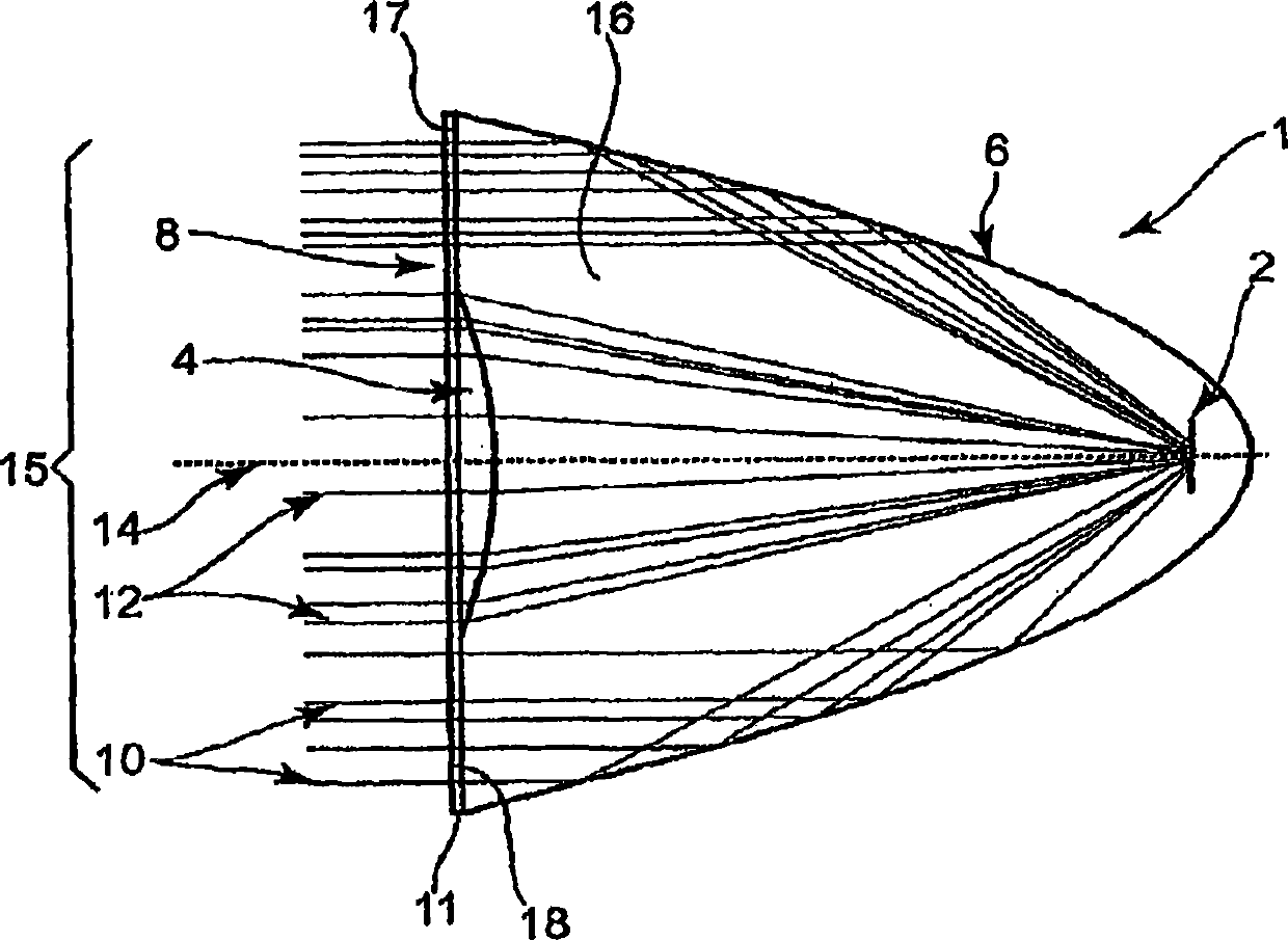
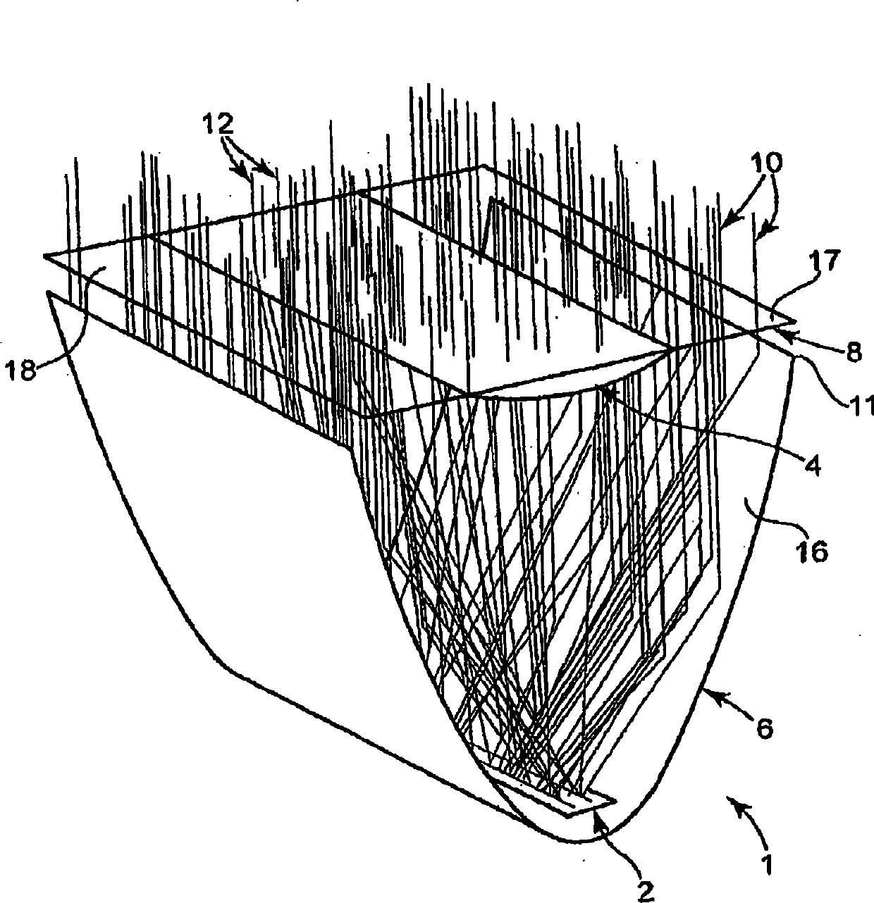
[0033] Figure 1a, Figure 1b and Figure 7 A preferred embodiment of the hybrid primary optic 1 of the invention is shown. For illustration purposes, the optical component 1 is in the form of a linear concentrator. The full aperture 15 of the component 1 spans the width (in the case of a line concentrator) or the diameter (in the case of a point concentrator) of the light receiving end 11 of the reflective element in the form of a bottom focusing dish 6 . This hybrid primary optic 1 includes a top cover 8 fitted onto a light receiving end 11 . The top cover 8 and tray 6 together provide a...


PUM


Abstract

A hybrid optical component collects and concentrates incident light. The hybrid component includes both refractive and reflective elements. In preferred embodiments, refractive and reflective components focus rays on a common focal plane generally located at the bottom of the reflector where they are absorbed by a device such as a photovoltaic (solar) cell. Additionally, the optical component combines both imaging and non-imaging optical elements into a single device, for improved overall performance.

Description

[0001] priority claim [0002] Pursuant to 35 U.S.C. §119(e), this nonprovisional patent application claims the patent application filed on January 17, 2006 by Hines et al., entitled A HYBRID PRIMARY OPTICAL COMPONENT FOR OPTICAL CONCENTRATORS ), which is incorporated herein by reference in its entirety. technical field [0003] The present invention relates to optical arrangements applied to optical concentrating systems such as line or point solar collectors that receive and concentrate incident light onto a target(s). The target may be a device such as a photovoltaic (solar) cell. Background technique [0004] An optical concentrating system, such as a solar collector, concentrates light toward the focal point of the optical system. Generally, there are two types of concentrators. Line condensers focus incident light in one dimension so that the focus is a line. A point concentrator concentrates incident light in two dimensions so that the focal point is a point. [...

Claims


Application Information

Patent Timeline
Patent Type & Authority Applications(China)
IPC IPC(8): F24J2/08F24J2/10F24J2/12F24J2/14H01L31/052F24S23/30F24S23/70F24S23/71F24S23/74
CPCF24J2/08F24J2/14Y02E10/52G02B19/0028H01L31/0522F24J2/085G02B19/0042F24J2/12F24J2/06Y02E10/42Y02E10/44Y02E10/45G02B17/0876G02B3/08F24S23/00F24S23/30F24S23/31F24S23/71F24S23/74H01L31/0543H01L31/0547G02B5/10H02S40/22Y02E10/40
Inventor B·E·海尼斯小R·L·约汉逊
Owner SOLIANT ENERGY INC
Why Eureka
Try Eureka