Device for transporting grain used on feeding-wheel device

A technology of conveying device and feeding wheel, which is applied in application, agricultural machinery and implements, harvesters, etc. It can solve the problems of troublesome replacement and maintenance, easy aging, and many contact surfaces, so as to achieve less replacement and maintenance and less failure rate , long service life effect

Inactive Publication Date: 2009-03-04
GUANGDONG KOLEA MODERN AGRI EQUIP
View PDF0 Cites 0 Cited by
  • Summary
  • Abstract
  • Description
  • Claims
  • Application Information

AI Technical Summary

Problems solved by technology

Among them, the ear conveying device is composed of a belt guide wheel and a conveyor belt installed on the belt guide wheel. The belt guide wheel and the toothed feeding wheel are coaxially installed on the feeding wheel shaft. The conveyor belt in this ear conveying device consists of The belt is composed of a protruding claw set on the belt, such as the harvester produced by Kubota in Japan. The belt is installed on the belt guide wheel and the tensioning wheel. When working, the belt is elliptical. Under the action of the tensioning wheel, the belt is formed by The belt guide wheel drives the movement, and the protruding claws also move accordingly, so that the ears of the harvested corn stalks are gathered and transported slightly backward under the embrace of the protruding claws. This type of ear conveying device, during the operation process, the protruding claws Both the belt and the belt are subject to wear, especially the wear of the belt. Because of its many contact surfaces, the wear is aggravated, and the working environment is harsh, it is also prone to aging and affects the rotation of the belt. In addition, the tension pulley is also a part that is prone to failure. Therefore, it is also easy to cause the belt to not work normally, and if the belt does not work normally, it will directly affect the work of the protruding claws.
When the tensioner fails, the belt is aging or the belt is seriously worn, it is very troublesome to replace and repair

Method used


Image

  • Device for transporting grain used on feeding-wheel device
  • Device for transporting grain used on feeding-wheel device

Examples


Embodiment Construction

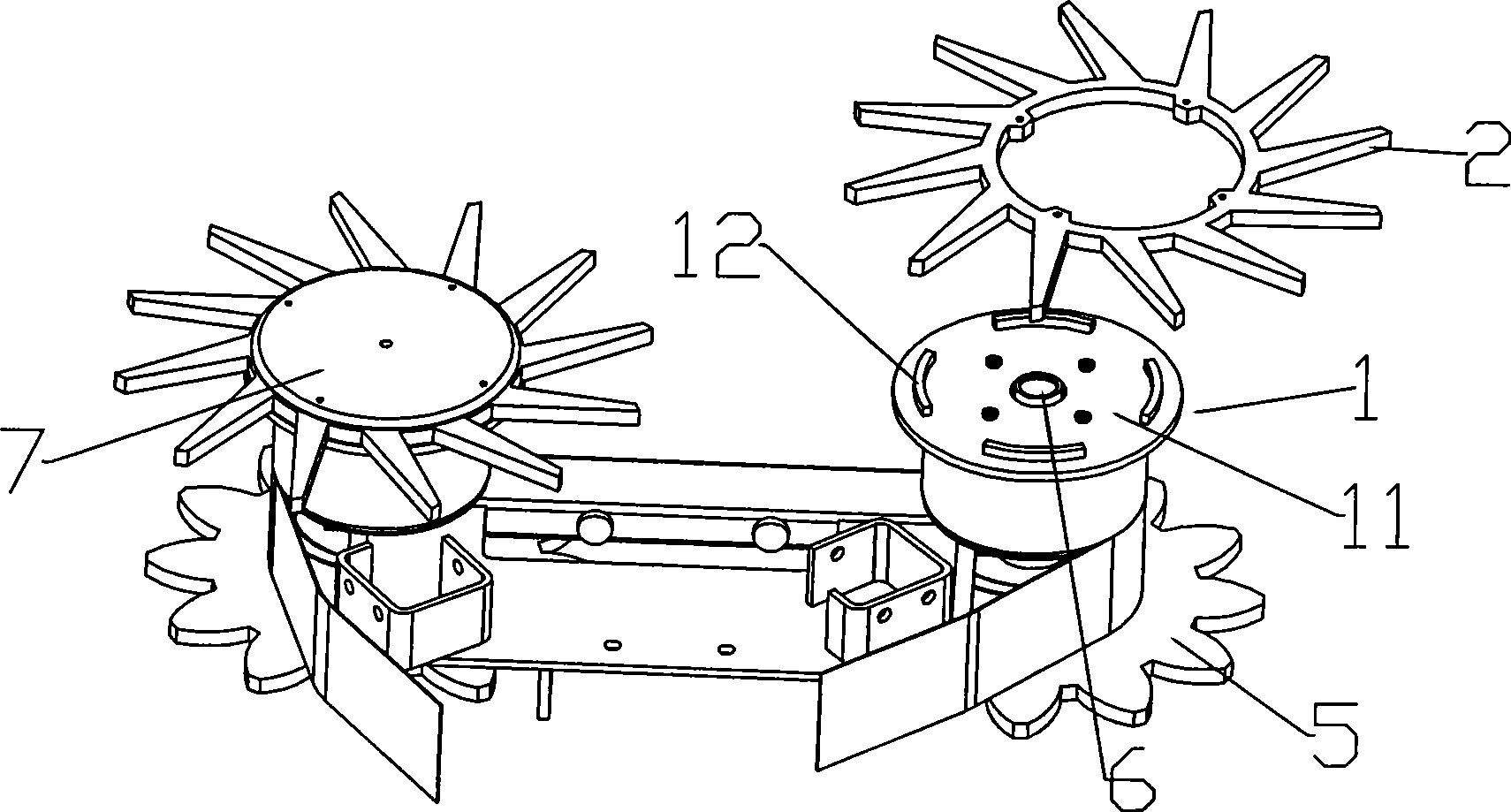
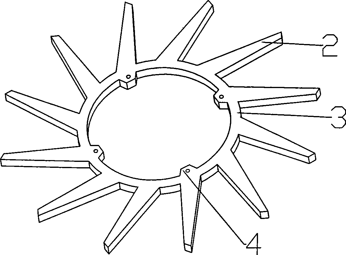
[0018] Below in conjunction with accompanying drawing the present invention is used for the ear conveying device on the feeding wheel device to be further described:

[0019] Such as figure 1 , figure 2 As shown, the present invention is used for the ear conveying device on the feeding wheel device, including a belt guide wheel 1 coaxially installed on the feeding wheel shaft 6 with the toothed feeding wheel 5, a conveying protruding claw 2, and a belt guide wheel 1 Coaxial disc 11 is provided on the top, and conveying protruding claw 2 is fixed on the disc 11 of belt guide wheel 1, and each conveying protruding claw 2 takes the rotating shaft center of belt guide wheel 1 as the center of symmetry and is distributed in a divergent shape at equal intervals. Each conveying claw 2 can also be fixed on the disc 11 of the belt guide wheel 1 by the belt 3, and each conveying claw 2 and the belt 3 are integrally made of the same piece of material. The belt 3 is annular, and each c...


PUM


Abstract

The invention discloses an ear transportation device used for a feed beater device. The ear transportation device comprises a belt guide wheel which is coaxially mounted on the axes of the feed beater with a dentation feed beater. The belt guide wheel is provided with a coaxial disk. The ear transportation device is characterized in that the ear transportation device further comprises transportation projecting claws; the transportation projecting claws are fixed on the disk of the belt guide wheel; the transportation projecting claws take the center of a rotating shaft of the belt guide wheel as the symmetrical center and are divergently distributed in uniform spacing; the transportation projecting claws are fixed on the disk of the belt guide wheel through a belt and are integrated with the belt; the number of the transportation projecting claws is twelve, the number of dummy clubs is four, and the number of arc-shaped lug bosses is four; and a belt cover is mounted on the belt. The invention has the advantages of fewer fault rates, and lesser replacement and maintenance phenomena. Therefore, the ear transportation device greatly reduces the use cost.

Description

technical field [0001] The invention relates to the field of combine harvesters, in particular to a technology for the ear conveying device on the feeding wheel device. Background technique [0002] On the front of the harvester, there is generally a cutting device in the shape of a hair clipper for cutting off the raised upright grain stem rhizome, a feeding wheel device that collects and transports the root of the harvested grain stem backward, and is installed on the feed wheel. On the device, the ears of harvested grain stalks are collected and conveyed slightly backward, and the grain stalks conveyed to the rear threshing device while changing the collected and transported harvested grain stalks from an upright state to a horizontal state. Among them, the ear conveying device is composed of a belt guide wheel and a conveyor belt installed on the belt guide wheel. The belt guide wheel and the toothed feeding wheel are coaxially installed on the feeding wheel shaft. The c...

Claims


Application Information

Patent Timeline
Patent Type & Authority Applications(China)
IPC IPC(8): A01D61/02A01D57/26
Inventor 彭康益
Owner GUANGDONG KOLEA MODERN AGRI EQUIP
Why Eureka
Try Eureka