
Method and device for forming internal gear

An internal gear and tooth profile technology, applied in the field of internal gear forming and forming devices, can solve the problems of poor strength and durability of parts, unqualified, and high degree of

Inactive Publication Date: 2009-03-04
NIHON SPINDLE MFG CO LTD
View PDF2 Cites 12 Cited by
  • Summary
  • Abstract
  • Description
  • Claims
  • Application Information

AI Technical Summary

Problems solved by technology

[0004] However, in this case, sometimes Figure 5 The Z1 part shown, that is, in the processed internal gear, there will be a shortage of material caused by material shrinkage at the inner corner of the cup-shaped blank, and the strength and durability of the part are poor, and at the same time Problems such as failure in product inspection due to high degree of material shortage

Method used


Image

  • Method and device for forming internal gear
  • Method and device for forming internal gear
  • Method and device for forming internal gear

Examples


Embodiment 1

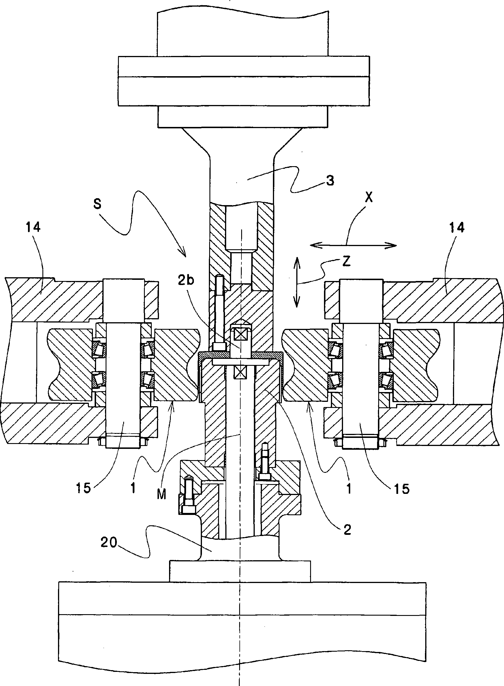
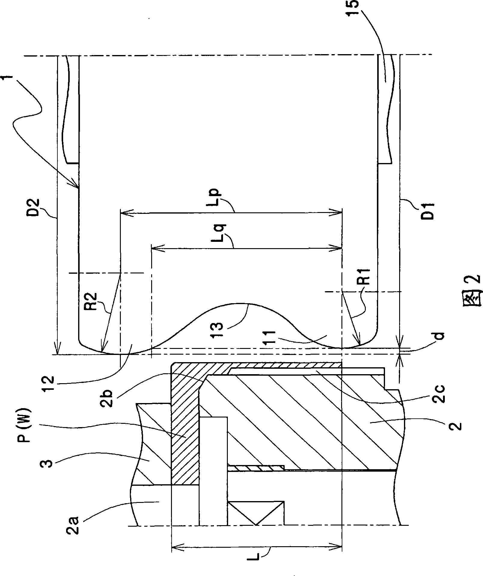
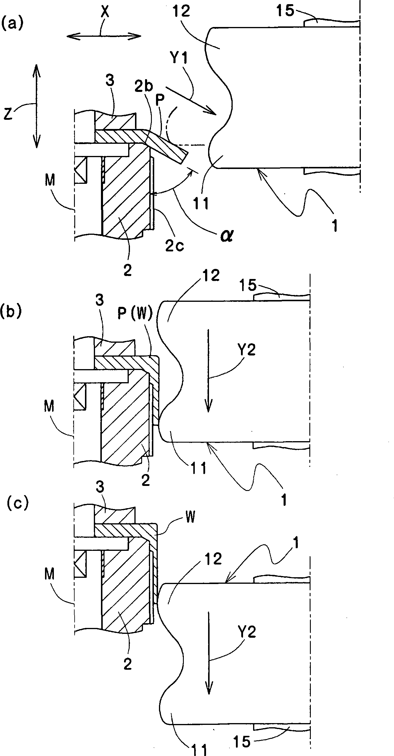
[0021] Figure 1 ~ Figure 3 An example of the forming method and forming apparatus of the internal gear of the present invention is shown.

[0022] This internal gear forming device installs a disc-shaped blank P on a mandrel 2 having a tooth profile 2c on the peripheral surface, and uses circular arc portions R1, R2, and Compared with the outer diameter D1 of the arc portion R1 that first contacts with the disc-shaped blank P, the drawing roll 1 whose outer diameter D2 of the arc portion R2 in contact with the latter is increased, so that the drawing roll 1 is in contact with the mandrel. 2 moves in a direction parallel to the axis center to form a cylindrical internal gear W.

[0023]This internal gear shaping device S consists of a spindle 2 having a tooth shape 2c on the outer peripheral surface provided on the front end of a rotating main shaft 20, a pressing member 3 provided opposite to the spindle 2, and a pair of shafts mounted on the spindle. The shaft 2 is compose...


PUM


Abstract

A inner gear forming method can ensure no shortened cycle caused by material shortage even in inner gear forming to thin walled blank by plastic working. In the inner gear (W) forming method for forming cylindrical inner gear (W) by mounting blank (P) on the mandrel (2) which has gear form (2C) on circumference and pushing the depth drawing roller (1) to the blank (P), a depth drawing roller (1), which has arc sections (R1, R2) contacting with the blank (P) on two positions while the outside diameter (D2) of the second contacting arc section (R2) is smaller than that of the first contacting one, is used to form the cylindrical inner gear (W) by moving it along the direction along the axes (M) of the mandrel (2).

Description

technical field [0001] The present invention relates to a forming method and a forming device of an internal gear, and particularly to a method and a forming device capable of forming a good internal gear without lack of material even by plastic working. Background technique [0002] Among the existing methods of forming internal gears, the method of plastic working generally adopts the method of using a cup-shaped blank in advance to cover the outer peripheral surface with teeth. It is mounted on a mandrel with a shape, and is plastically processed by pushing with a drawing roll. However, in this case, steps such as press working are required as a step of forming the blank into a cup shape, and there is a problem that it takes a lot of time to manufacture each product. [0003] Therefore, as a method of forming an internal gear while directly forming a cup shape from a circular plate-shaped blank by plastic working using a spinning device, there has been adopted a method ...

Claims


Application Information

Patent Timeline
Patent Type & Authority Applications(China)
IPC IPC(8): B21D53/28B21D22/16
Inventor 饭尾良夫岸野纯治
Owner NIHON SPINDLE MFG CO LTD
Learn More