Multi-part cast turbine engine component having an internal cooling channel and method of forming the same

A cooling channel and multi-component technology, applied in the direction of blade support components, mechanical equipment, engine components, etc., can solve the problems of residual core, displacement and damage, poor grain orientation, etc., and achieve easy formation and easy goal The effect of visual inspection

Inactive Publication Date: 2009-03-04
GENERAL ELECTRIC CO
View PDF6 Cites 11 Cited by
  • Summary
  • Abstract
  • Description
  • Claims
  • Application Information

AI Technical Summary

Problems solved by technology

Also, ceramic cores are brittle and prone to shifting and breakage
Finally, the inner surface of the channel may contain residual core defects, poor grain orientation or finning
The manufacturing method described above makes it difficult, if not impossible, to visually inspect the channels

Method used


Image

  • Multi-part cast turbine engine component having an internal cooling channel and method of forming the same
  • Multi-part cast turbine engine component having an internal cooling channel and method of forming the same
  • Multi-part cast turbine engine component having an internal cooling channel and method of forming the same

Examples


Embodiment Construction

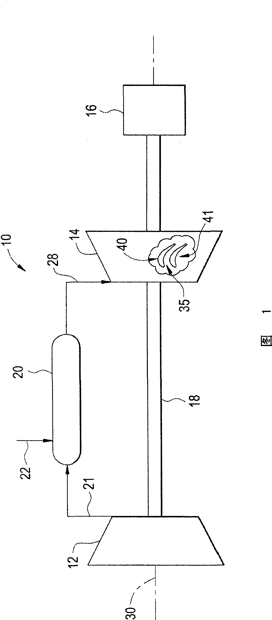
[0011] Referring first to FIG. 1 , there is indicated generally at 10 a gas turbine engine constructed in accordance with the present invention. Gas turbine engine 10 includes a compressor 12 operably coupled to a turbine 14 and a generator 16 via a shaft 18 . Shaft 18 is illustrated as a single unitary member, however, it should be understood that shaft 18 could also be formed from multiple segments, with each segment coupled to an adjacent engine component.

[0012] In any event, engine 10 is also shown to include combustion chamber 20 in which air 21 from compressor 12 mixes with fuel 22 to form a combustible mixture. The combustible mixture is ignited to form high pressure, high temperature combustion products or gases 28 that are used to drive turbine 14 . More specifically, high pressure, high temperature gas 28 enters turbine 14 and impinges on rotor assembly 35 having a plurality of rotor blades, two of which are designated 40 and 41 . The rotor assembly 35 converts ...


PUM


Abstract

A multi-part cast component for a turbine engine includes a first component section having a main body portion including at least one cooling flow passage section, and a second component section having a main body including at least one cooling flow passage section. The first and second component sections are joined along a parting line to form a turbine engine component with the at least one cooling flow passage section of the first component section aligning with the at least one cooling flow passage of the second component section to form a cooling flow channel.

Description

technical field [0001] The present invention relates to the field of turbine engines, and more particularly, the present invention relates to two-part cast turbine engine components having internally formed cooling cavities. Background technique [0002] In general, a gas turbine engine combusts a fuel / air mixture to release heat energy in the form of a high temperature gas flow that is directed to a turbine section via a hot gas path. More specifically, the compressor compresses incoming air to a high pressure. The high pressure air is delivered to the combustion chamber to mix with fuel and form a combustible mixture. The combustible mixture is then ignited to form a high-pressure, high-velocity gas stream that is delivered to a turbine. The high pressure air impinges on rotor blades or buckets that form part of the turbine rotor assembly. In this way, the turbine converts thermal energy from the high-temperature, high-speed airflow into mechanical energy that rotates t...

Claims


Application Information

Patent Timeline
Patent Type & Authority Applications(China)
IPC IPC(8): F01D5/18
CPCF01D5/187F05D2230/211F05D2230/23Y10T29/49341
Inventor T·穆尔斯
Owner GENERAL ELECTRIC CO
Why Eureka
Try Eureka