Radio frequency identification positioning apparatus and method

A radio frequency identification and positioning device technology, applied in the direction of instruments, loop antennas, induction record carriers, etc., can solve the problems that resonance is not easy to occur, it is difficult to correctly sense and identify signals, and the induction coil cannot reach the matching state, etc.

Inactive Publication Date: 2009-03-04
G TIME ELECTRONICS
View PDF0 Cites 10 Cited by
  • Summary
  • Abstract
  • Description
  • Claims
  • Application Information

AI Technical Summary

Problems solved by technology

[0004] The disadvantage of the above-mentioned conventional technology is that the lines of the radio frequency identification positioning device 11 are not roughly equal in length, so the induction coils in the antenna induction group 113 cannot reach a matching state, and resonance is not easy to occur, so that the antenna induction group 113 and the capacitor 114 are in the same state. When the magnetic flux is high, it is difficult for the antenna induction group 113 to correctly sense the identification signal of the radio frequency identification tag 12
In addition, because there is only one antenna induction group 113 in the radio frequency identification positioning device 11, the magnetic flux generated by the antenna induction group 113 is relatively weak, and the induction ability is also relatively poor.
Moreover, the radio frequency identification positioning device 11 has only one switching group 112, which will also cause the detection circuit 115 to receive two identification signals at the same time, making it difficult to identify and locate the radio frequency identification tag 12
In addition, the radio frequency identification positioning device 11 has no grounding function, so that the magnetic fields generated by the induction coils in the antenna induction group 113 interfere with each other

Method used


Image

  • Radio frequency identification positioning apparatus and method
  • Radio frequency identification positioning apparatus and method
  • Radio frequency identification positioning apparatus and method

Examples


Embodiment Construction

[0046] In order to make the above-mentioned purpose, features and advantages of the present invention more obvious and easy to understand, the radio frequency identification positioning device and its method according to the present invention will be described below in detail with preferred embodiments, together with the attached relevant diagrams, as follows: The same elements will be described with the same element symbols.

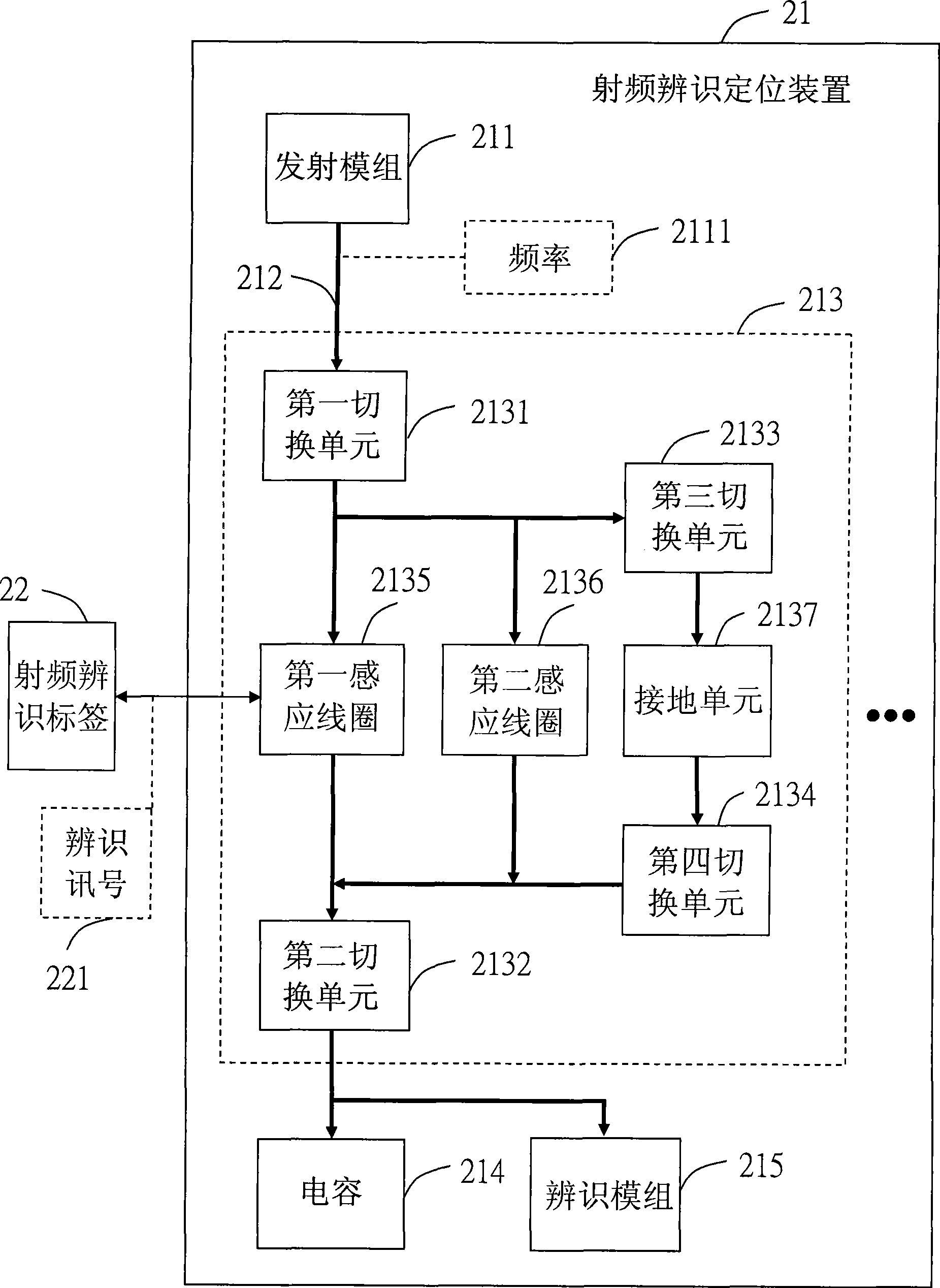
[0047] see figure 2, is a schematic diagram showing the radio frequency identification positioning device of the present invention. In the figure, the radio frequency identification positioning device 21 can identify and locate at least one radio frequency identification tag 22, and includes a transmitting module 211, at least one capacitor 214, a plurality of sensing modules, an identification module 215 (such as a detection circuit) and A plurality of line modules. Wherein, the transmitting module 211 transmits a frequency 2111 . Furthermore, the ...


PUM


Abstract

The invention discloses a radio frequency identification locating device and a method thereof, which can identify and locate at least one radio frequency identification tag. The device comprises an emitting mould train, a capacitor, a plurality of pairs of induction mould trains, an identification mould train and a plurality of pairs of line mould trains. The emitting mould train emits a frequency. The first switch units of the induction mould trains carry out conduction according to the frequency so that a first induction coil forms a flux with the capacitor, and the first induction coil induces the identification signals of the radio frequency identification tags. A second induction coil is used for improving the flux. The identification mould train receives the identification signals for identifying and locating the radio frequency identification tags. Each line mould train is connected with the emitting mould train, the induction mould trains, the capacitor and the identification mould train, and transmits the identification signals. All of the induction coils are matched with each other by virtue of the approximately equal length of each line mould train.

Description

technical field [0001] The present invention provides a radio frequency identification positioning device and its method, especially the radio frequency identification positioning device which allows the length of each line module to be roughly equal, so that the induction coil reaches a matching state, so as to identify and locate radio frequency identification tags. Background technique [0002] Radio Frequency Identification System (Radio Frequency Identification System, RFID) has radio frequency and identification functions, and does not need to be in direct contact with objects. As long as it is within the range of radio frequency signal sensing, it can read the identification signal in the radio frequency identification tag to identify Objects or data content, so it is often used for identification purposes. However, since the radio frequency identification system usually only has the identification function but not the positioning function, its practical application i...

Claims


Application Information

Patent Timeline
Patent Type & Authority Applications(China)
IPC IPC(8): G06K7/00
CPCH01Q1/2216H01Q3/24H01Q7/00G06K7/10336G06K7/10079G06K2017/0045G06K7/10356H01Q21/061
Inventor 侯天发吴哲铭吴盈锋
Owner G TIME ELECTRONICS
Why Eureka
Try Eureka