Thermal stimulation apparatus for vehicles

A thermal stimulation and vehicle technology, applied to special positions of vehicles, hypnotic devices, vehicle components, etc., can solve problems such as improving the physical fitness of passengers, and achieve the effects of reducing fatigue, improving biological functions, and increasing temperature changes

Inactive Publication Date: 2009-03-04
TOYOTA JIDOSHA KK
View PDF3 Cites 4 Cited by
  • Summary
  • Abstract
  • Description
  • Claims
  • Application Information

AI Technical Summary

Problems solved by technology

[0007] However, in the examples described in Patent Document 1 and Patent Document 2, it is not considered that the effects of reducing passenger fatigue and improving the physical fitness of passengers are obtained by applying thermal stimulation to passengers on the vehicle.
Therefore, there is still room for improvement in order to make it possible to bring effects such as reducing fatigue and improving physical fitness to passengers on the vehicle.

Method used


Image

  • Thermal stimulation apparatus for vehicles
  • Thermal stimulation apparatus for vehicles
  • Thermal stimulation apparatus for vehicles

Examples


no. 1 approach

[0053] The thermal stimulation device 10 for a vehicle in the first embodiment of the present invention will be described below.

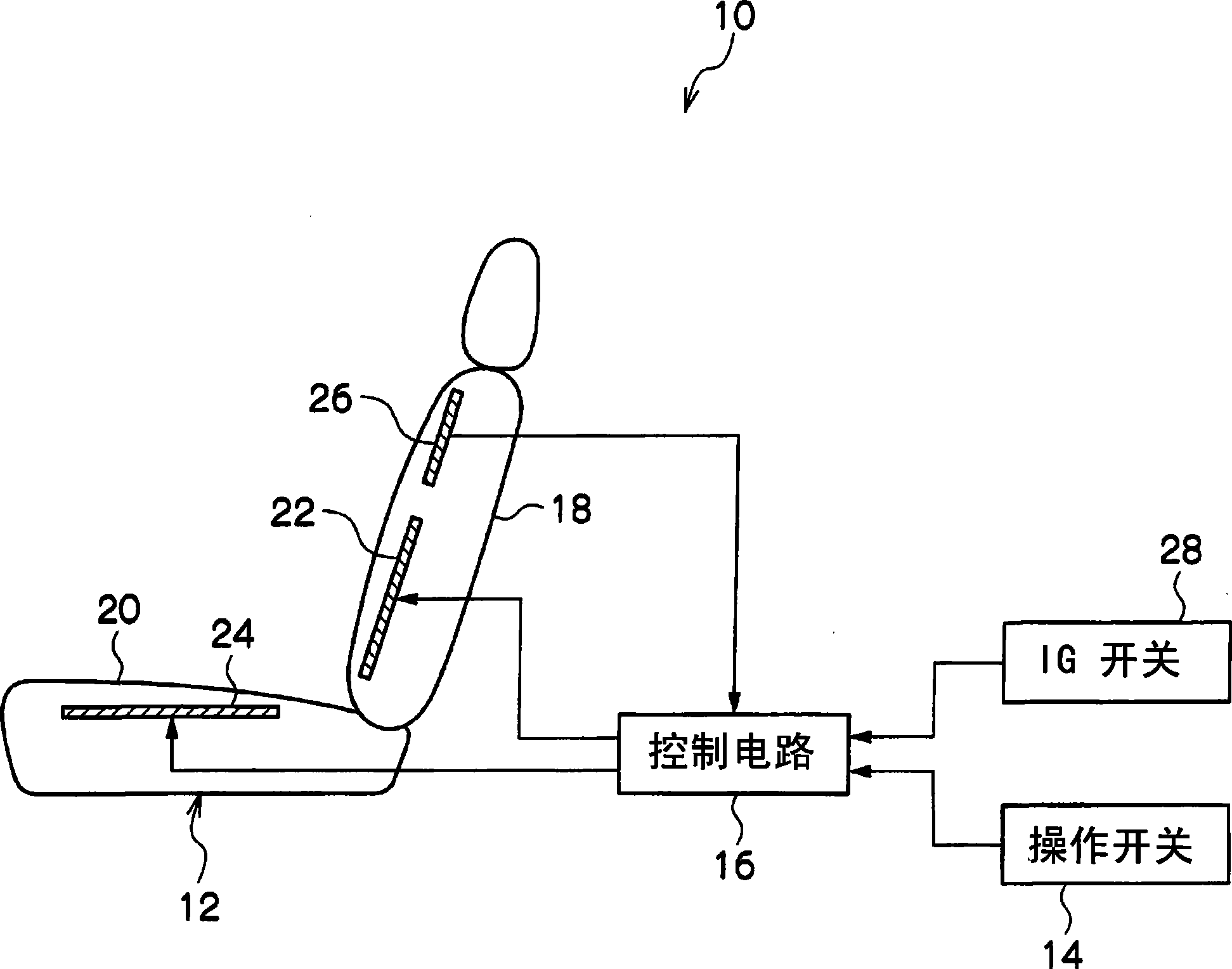
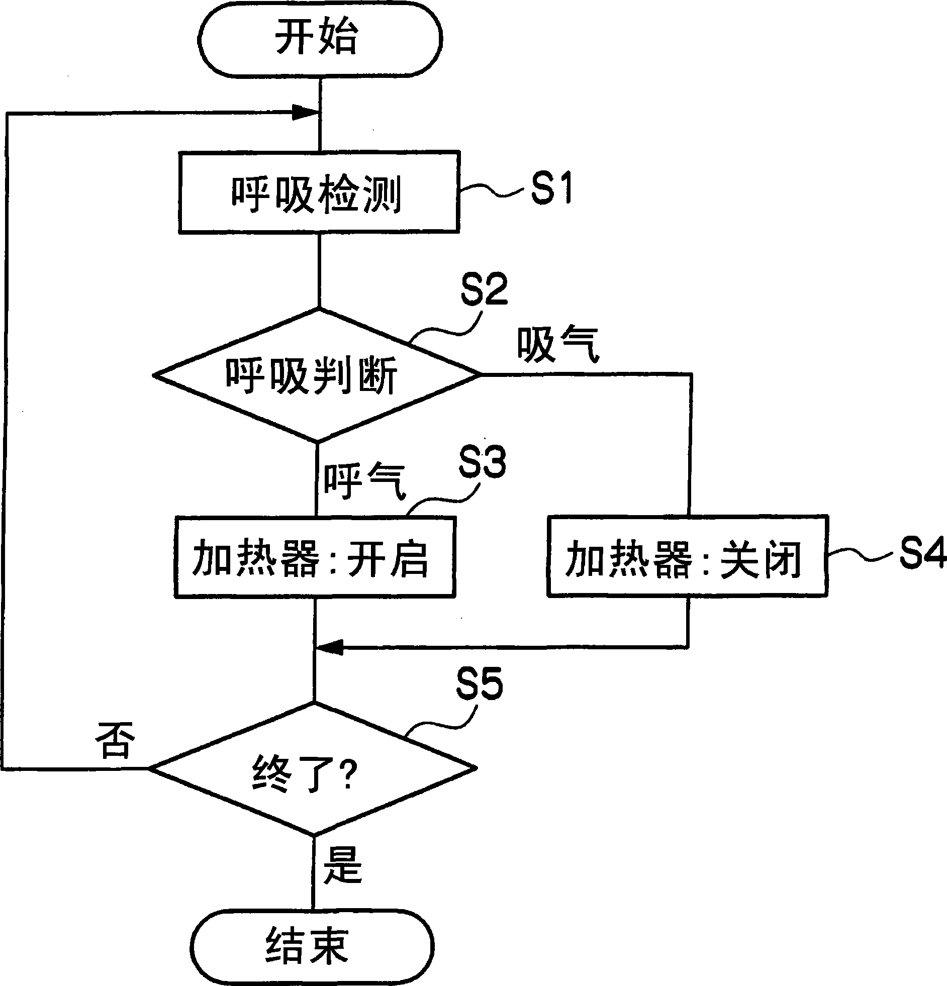
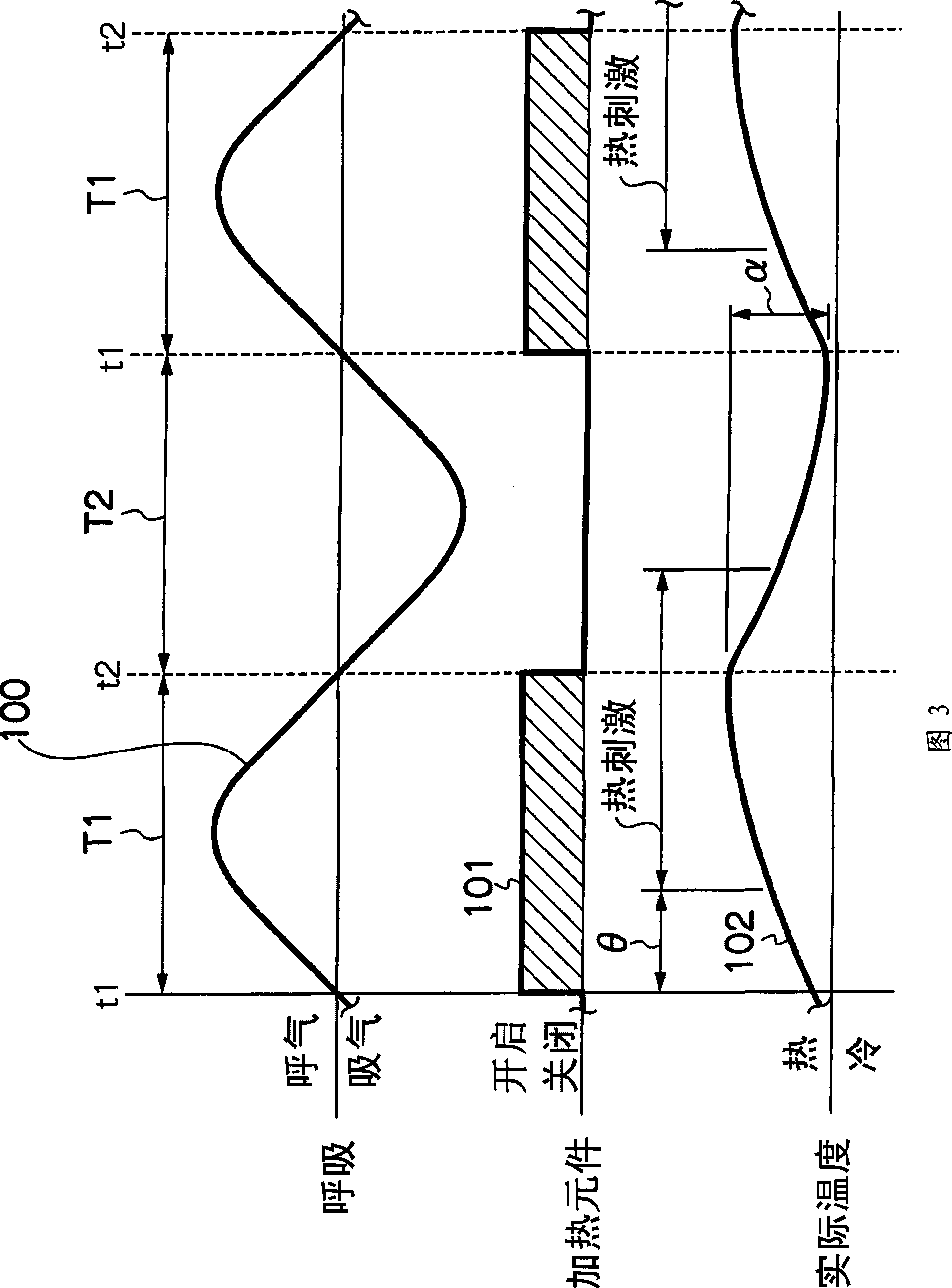
[0054] exist figure 1 , figure 2 , FIG. 3 respectively illustrate the first embodiment, wherein, figure 1 It is a block diagram showing the overall structure of the thermal stimulation device 10 for a vehicle in the first embodiment of the present invention; figure 2 It is a working flow diagram of the vehicle thermal stimulation device 10 in the first embodiment of the present invention; FIG. 3 is a working sequence diagram of the vehicle thermal stimulation device 10 in the first embodiment of the present invention.

[0055] Such as figure 1 The shown thermal stimulation device 10 for a vehicle in the first embodiment of the present invention is a device suitable for vehicles such as passenger cars, and its main components include a vehicle seat 12, an operation switch 14, and a control unit as a control unit. The control circuit 16.

[00...

no. 2 approach

[0080] Hereinafter, the thermal stimulation device 50 for a vehicle in the second embodiment of the present invention will be described.

[0081] exist Figure 5 , Figure 6 , FIG. 7 respectively illustrate the second embodiment, wherein, Figure 5 It is a block diagram showing the overall structure of the thermal stimulation device 50 for a vehicle in the second embodiment of the present invention; Figure 6 It is a working flow diagram of the vehicle thermal stimulation device 50 in the second embodiment of the present invention; FIG. 7 is a working sequence diagram of the vehicle thermal stimulation device 50 in the second embodiment of the present invention.

[0082] in such as Figure 5 In the shown thermal stimulation device 50 for a vehicle in the second embodiment of the present invention, the heating and cooling units 42 and 44 as thermal stimulation generating units are provided instead of the thermal stimulation device 10 for a vehicle in the first embodiment of ...

no. 3 approach

[0103] Hereinafter, a thermal stimulation device 60 for a vehicle in a third embodiment of the present invention will be described.

[0104] exist Figure 9 , Figure 10 , FIG. 11 and FIG. 12 respectively illustrate the third embodiment, wherein, Figure 9 is a block diagram showing the overall structure of the thermal stimulation device 60 for a vehicle in the third embodiment of the present invention; Figure 10 It is a working flow chart of the thermal stimulation device 60 for vehicles in the third embodiment of the present invention; Figure 11A , Figure 11B It is an explanatory diagram of the operation of the vehicle thermal stimulation device 60 in the third embodiment of the present invention; FIG. 12 is a working sequence diagram of the vehicle thermal stimulation device 60 in the third embodiment of the present invention.

[0105] in such as Figure 9In the thermal stimulation device 60 for a vehicle in the third embodiment of the present invention shown, a mov...


PUM


Abstract

It is intended to provide a thermal stimulation apparatus for vehicles which can exert effects of, for example, reducing fatigue and improving physical conditions on a crew member in a vehicle. In a thermal stimulation apparatus for vehicles (10), when the biorhythm (for example, respiration rhythm) with periodical changes of a crewmember is detected by a piezoelectric sensor (26), heater elements (22, 24) are switched on by a control circuit (16) based on the detection data and thus thermal stimuli synchronizing the respiration rhythm of the crew member are provided to the crew member by switching on / off the heater element (22, 24). As a result, the autonomic nerve (parasympathetic nerve) activity of the crew member can be enhanced. Therefore, it becomes possible to exert effects of, for example, reducing fatigue and improving physical conditions on a crew member in a vehicle.

Description

technical field [0001] The invention relates to a thermal stimulation device for a vehicle, in particular to a thermal stimulation device for a vehicle capable of applying thermal stimulation to passengers on the vehicle. Background technique [0002] For a long time, the following products have been known as heating devices (for example, refer to Patent Document 1 and Patent Document 2). For example, in Patent Document 1, an example of a vehicle heater is disclosed. In the example described in this Patent Document 1, a plurality of heaters are dividedly installed on a vehicle seat, and the heat generation values ​​of the plurality of heaters are changed. In addition, by intensively heating the parts of the human body that are prone to temperature stimulation, the effect of bringing rapid heating to the passengers is achieved. [0003] Furthermore, for example, in Patent Document 2, an example of an electric blanket is disclosed. In the example described in this Patent Do...

Claims


Application Information

Patent Timeline
Patent Type & Authority Applications(China)
IPC IPC(8): A61M21/02A61F7/00A47C21/04
CPCA61M2230/42B60N2/5685A61M21/02A61M2205/3653B60H1/00742B60N2/002A61M2021/0066A61F7/007A61B5/18A61F7/00A47C21/04
Inventor 服部恒司
Owner TOYOTA JIDOSHA KK
Why Eureka
Try Eureka