Welding method of thermonuclear reactor experiment cladding modular unit assembly

An experimental cladding module and component assembly technology, applied in welding equipment, laser welding equipment, electron beam welding equipment, etc.

Inactive Publication Date: 2009-03-11
INST OF PLASMA PHYSICS CHINESE ACAD OF SCI
View PDF0 Cites 8 Cited by
  • Summary
  • Abstract
  • Description
  • Claims
  • Application Information

AI Technical Summary

Problems solved by technology

[0003] The purpose of the present invention is to solve the problem of assembling and manufacturing fusion reactor experimental cladding module components, and provide a welding method for assembling fusion reactor experimental cladding module components

Method used


Image

  • Welding method of thermonuclear reactor experiment cladding modular unit assembly
  • Welding method of thermonuclear reactor experiment cladding modular unit assembly
  • Welding method of thermonuclear reactor experiment cladding modular unit assembly

Examples


example 1

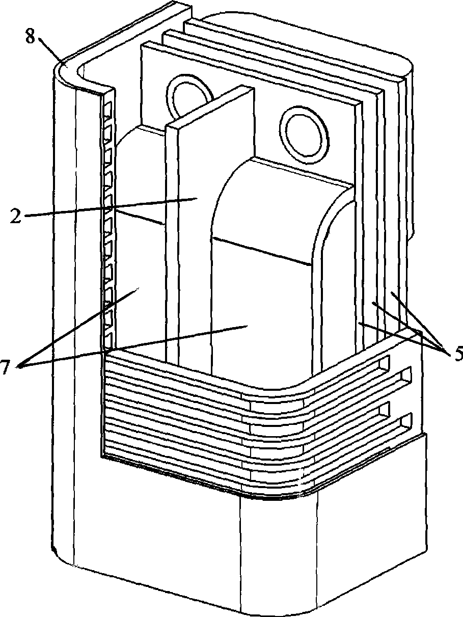
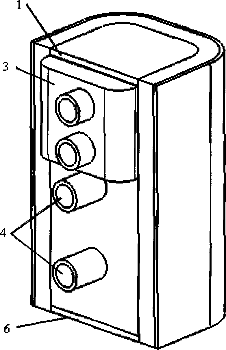
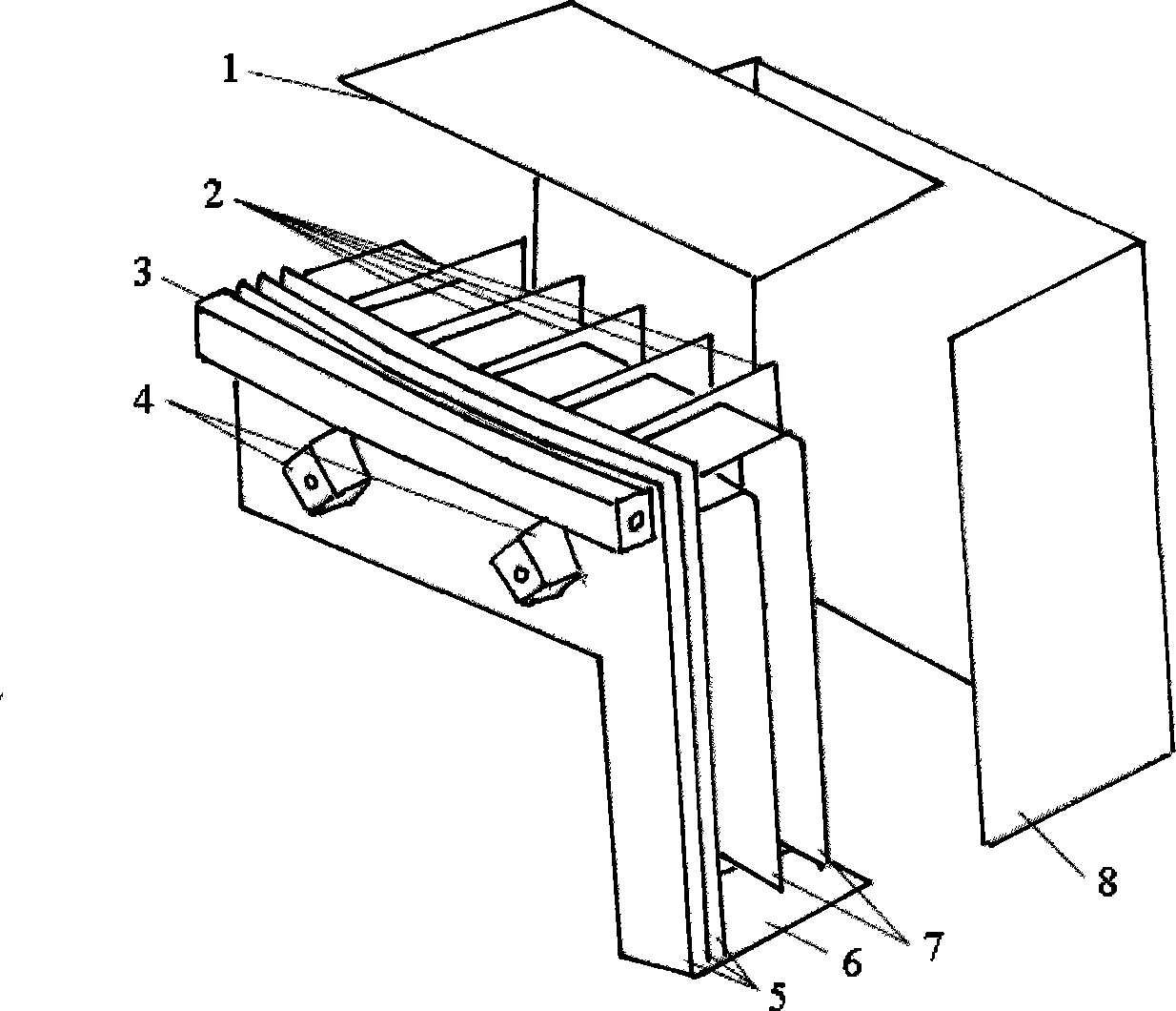
[0017] The welding method for assembling the fusion reactor experimental cladding module components includes the following steps in turn: a. welding the radial pole separator to the first wall; b. welding the ring pole in the area formed by the radial pole separator and the first wall Partition plate; c. Weld the upper cover plate and the lower cover plate to the first wall; d. Weld the back plate sequentially from the inside to the outside, and weld the branch pipes sequentially; e. Finally, weld the distribution / receiving box to the outermost back board. In this example laser welding is used.

[0018] The welding object in steps a and b is 10mm thick low-activation ferrite / martensitic steel; the welding parameters required for welding are: power 3-6kW; focus position 0-2mm; welding speed 0.3-2m / min, the protective gas is argon, and the flow rate of the protective gas is 1-101 / min.

[0019] The welding object in steps c and d is 5-35mm thick low-activation ferrite / martensi...

example 2

[0022] The welding method for assembling the fusion reactor experimental cladding module components includes the following steps in turn: a. welding the radial pole separator to the first wall; b. welding the ring pole in the area formed by the radial pole separator and the first wall Partition plate; c. Weld the upper cover plate and the lower cover plate to the first wall; d. Weld the back plate sequentially from the inside to the outside, and weld the branch pipes sequentially; e. Finally, weld the distribution / receiving box to the outermost back board. In this example electron beam welding is used.

[0023] The welding object in steps a and b is 10mm thick low-activation ferrite / martensitic steel; the welding parameters required for welding are: acceleration voltage is 55-60kV; electron beam current is 20-90mA; focusing current is 650-800mA ; Working distance is 140~200mm; welding speed is 10~14mm / s; vacuum degree is 5×10 -2 ~5×10 -3 Pa.

[0024] The welding object in ...

example 3

[0027] The welding method for assembling the fusion reactor experimental cladding module components includes the following steps in turn: a. Welding a radial pole separator to the first wall; b. After step a is completed, it is composed of the radial pole separator and the first wall 2 areas, weld 1 ring pole separator in each area, weld 2 ring pole separators in total; d, weld 3 back plates sequentially from inside to outside, and weld branch pipes in sequence. Other conditions and steps are the same as Example 1.


PUM


Abstract

The invention discloses a welding method for assembling the parts of a fusion reactor test blanket module and aims at solving the assembling and manufacturing problems for the parts of the test blanket module. The invention is characterized in that the welding steps comprise in sequence: a, a radical pole clapboard is welded on a first wall; b, an annular pole clapboard is welded in an area formed by the radical pole clapboard and the first wall; c, an upper cover plate and a lower cover plate are welded on the first wall; d, back plates and pipe branches are welded in sequence from the inside to the outside; e, finally, a dividing / receiving box is welded on the back plate at the outermost layer. The welding method has the advantages of simple technique, small welding deformation, programming manufacture process, and the like. The welding method is suitable for manufacturing the test blanket modules with various structural forms.

Description

technical field [0001] The invention relates to the field of welding technology, in particular to a welding method for assembling fusion reactor experimental cladding module components. Background technique [0002] The main function of the cladding of the fusion reactor is to convert the kinetic energy of the fusion product particles into heat energy while multiplying tritium to maintain the core fusion reaction. The experimental cladding module is the preview carrier of fusion reactor cladding related technologies. A schematic diagram of the structure of an experimental cladding module such as figure 1 As shown, its main components include the first wall, ring pole separator, radial pole separator, back plate, upper and lower cover plates, branch pipes, and distribution / receiving boxes, etc., and its structural materials generally use low-activated iron. Nutritic / martensitic steel. Depend on figure 1 It can be seen that the experimental cladding module composed of thes...

Claims


Application Information

Patent Timeline
Patent Type & Authority Applications(China)
IPC IPC(8): B23K31/02B23K26/40B23K15/00
Inventor 吴庆生黄群英李春京吴宜灿
Owner INST OF PLASMA PHYSICS CHINESE ACAD OF SCI
Why Eureka
Try Eureka