Deformable flying device

A flying car and car body technology, applied in the field of flying cars, can solve the problems of high energy consumption, poor performance, and low efficiency, and achieve the effects of low energy consumption, high power density, and high efficiency

Inactive Publication Date: 2009-03-11
刘新广
View PDF0 Cites 10 Cited by
  • Summary
  • Abstract
  • Description
  • Claims
  • Application Information

AI Technical Summary

Problems solved by technology

Although there are many design schemes and a variety of prototype vehicles have been produced, they are difficult to be practical due to major defects such as poor performance, low efficiency, and huge energy consumption that are difficult to overcome.

Method used


Image

  • Deformable flying device
  • Deformable flying device
  • Deformable flying device

Examples


Embodiment 1

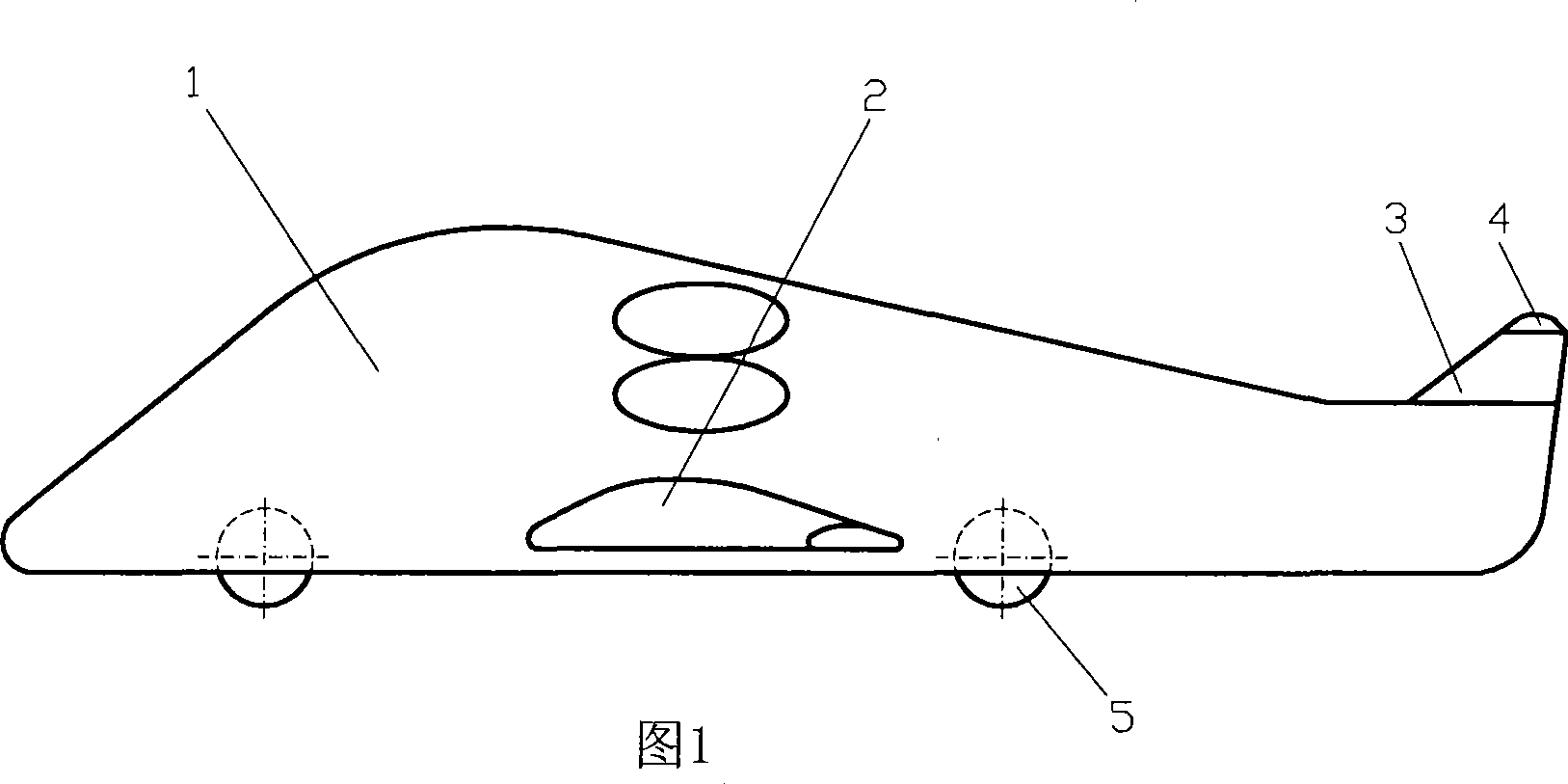
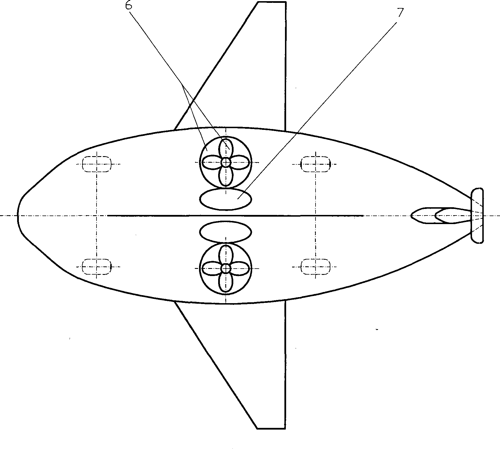
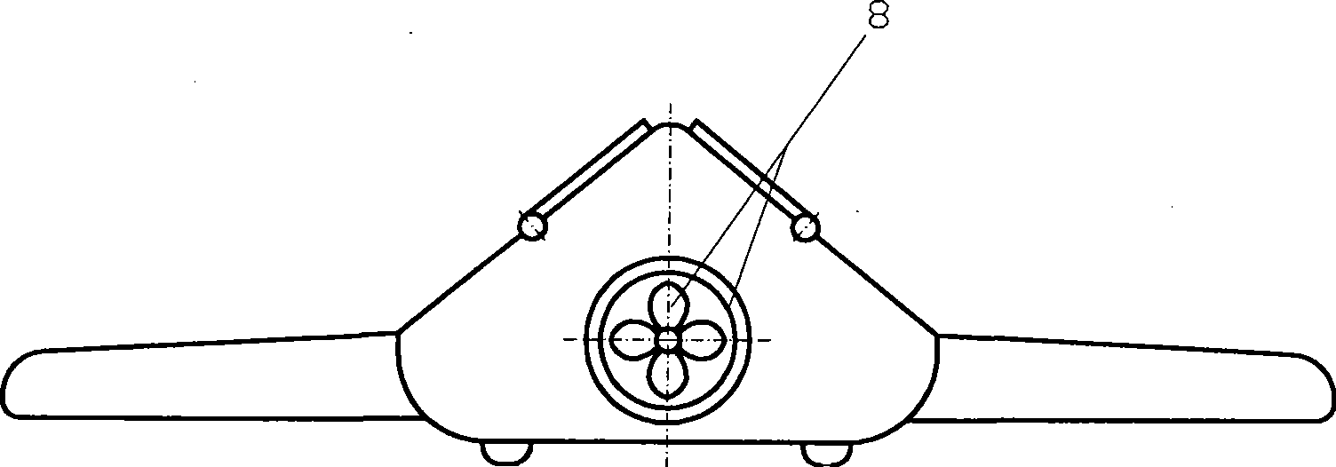
[0031] Embodiment one: as shown in Figure 1 to image 3 Show. Similar to the left and right sides of the body 1 of the fixed-wing aircraft fuselage, the car wing 2 that can be received in the body is set; a vertical empennage 3 and a horizontal empennage 4 are set at the rear of the body, and the horizontal empennage 4 is fixed on the vertical empennage 3, and can Take back and stick to the vertical empennage, the vertical empennage band rudder, or without rudder and set the compressed gas spout (not drawing) in the vertical empennage left and right sides; Four controllable motor-driven wheels 5 are set at the bottom of the vehicle body, or the motor It is integrated with the wheel 5; vertical ducted fans 6 are set on the left and right sides of the vehicle body 1, driven by any of the following controllable motors: permanent magnet motor, reluctance motor, permanent magnet energy machine, superconducting motor, superconducting motor etc., the vertical ducted fan 6 has a cont...

Embodiment 2

[0032] Embodiment two: as Figure 7 to Figure 12 Show. Vertical ducted fan 6 and its controllable drive motor and controllable split top cover 10 are set before and after the vehicle body 9 similar to the fixed-wing aircraft fuselage, and the selection of the motor is described in Embodiment 1; drop when open, such as Figure 10 When the flying car is driving on the road or flying in the air, it is closed to avoid the fan opening from disturbing the airflow and causing resistance, such as Figure 11 , Figure 12 Shown, when the flying car is parked, close the top cover 10 to prevent foreign objects from falling into; the horizontal propulsion engine 11 with rotation stop and speed controllable is set on the left and right sides of the vehicle body, and the selection of the horizontal propulsion engine is the same as that described in Embodiment 1; others are the same as in the embodiment one described.


PUM


Abstract

The invention relates to a deformable flying vehicle. Two sides of the left and the right of a vehicle body of a fixed wing aircraft are provided with wings which can be folded into the body. The tail of the body is provided with a vertical empennage and a horizontal empennage. The vertical empennage is provided with a rudder or is not provided with the rudder, and the left and the right of the vertical empennage are provided with a compressed air spouts. The bottom of the vehicle body is provided with a plurality of wheels which are driven by a controllable motor. The vehicle body is internally provided with a vertical ducted fan and also is provided with a horizontal thrust engine with controllable rotation pause and rotation speed. The compressed air is introduced from the horizontal thrust engine to the sprout through a control valve. The deformable flying vehicle achieves running, elevating, hovering and flying by controlling the wheels, the vertical ducted fan, the horizontal thrust engine, the wings and the empennages. The deformable flying vehicle has performance for both the ground and the air, is safe, flexible, economical and environmental protective for running and flying and is convenient for using.

Description

technical field [0001] The invention relates to a flying car, in particular to a deformed flying car. Background technique [0002] People have long wanted to invent a vehicle that can both drive on the road and fly in the air—a flying car. Although there are many kinds of design schemes and many prototype cars have been produced, they are difficult to be practical because of the major defects that are difficult to overcome such as poor performance, low efficiency and huge energy consumption. Designing and manufacturing a flying car that meets the requirements of land and air performance and consumes less energy has long tempted many scientists and engineers. Contents of the invention [0003] The invention discloses a deformed flying car, which has both ground and air performances, safe running and flying, flexible, economical, environment-friendly and convenient to use. [0004] The present invention is realized according to the following technical solutions. [0005]...

Claims


Application Information

Patent Timeline
Patent Type & Authority Applications(China)
IPC IPC(8): B60F5/02
Inventor 刘新广
Owner 刘新广
Why Eureka
Try Eureka