Main load-carrying structure of spacecraft

A spacecraft and main load-bearing technology, applied in the direction of aerospace vehicles, aircraft, space navigation equipment, etc., can solve the problems of not being able to adapt to the agile maneuvering of small satellites, not being able to meet the mobility of payloads, and difficult to realize the design and structure. To achieve the effect of compact structure, low center of mass and good overall rigidity

Active Publication Date: 2009-03-11
AEROSPACE DONGFANGHONG SATELLITE
View PDF0 Cites 64 Cited by
  • Summary
  • Abstract
  • Description
  • Claims
  • Application Information

AI Technical Summary

Problems solved by technology

However, when there is a heavy payload in the center of the satellite, it is not convenient to choose only the shell as the main force transmission structure.
[0011] The above-mentioned structures all adopt a single force transmission route, resulting in a large inertia of the longitudinal axis, and at the same time ca

Method used


Image

  • Main load-carrying structure of spacecraft
  • Main load-carrying structure of spacecraft
  • Main load-carrying structure of spacecraft

Examples


Embodiment Construction

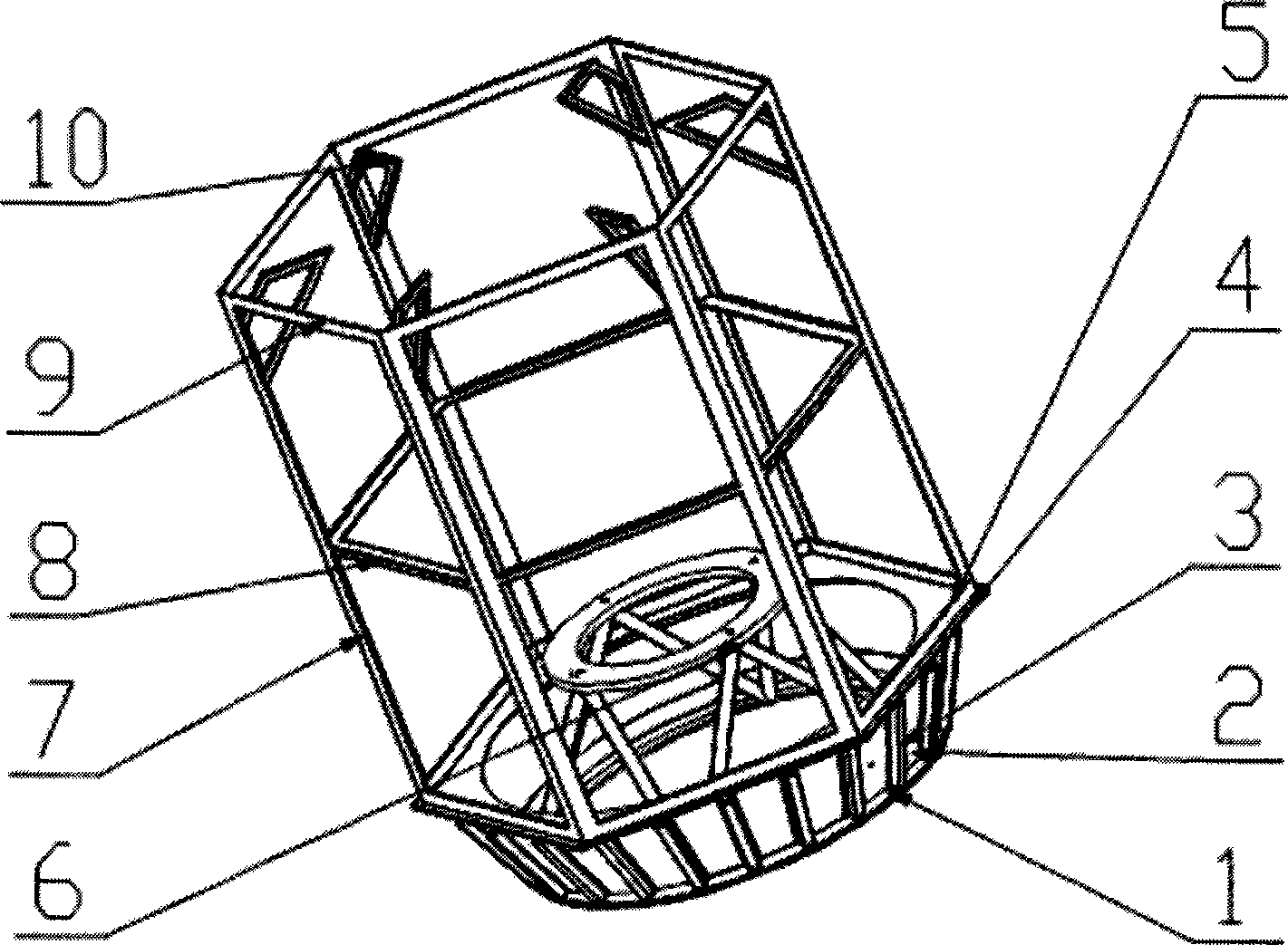
[0029] Such as figure 1 As shown, a new type of satellite main load-bearing structure of the present invention includes a propulsion cabin structure, a star truss structure and an electronic cabin main frame structure; the upper part of the propulsion cabin structure is connected to the electronic cabin main frame structure, and the lower part is used as a whole star precision detection benchmark surface and provide the installation surface for propulsion cabin instruments and equipment; the star-shaped truss structure is located in the main frame structure of the electronic cabin, and is a load installation frame supported by struts for installing payloads, and the lower ends of the struts are fixedly connected to the propulsion cabin upper part of the structure.

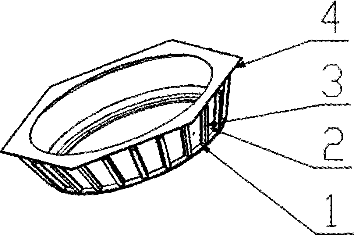
[0030] Such as figure 2 As shown, the structure of the propulsion cabin is in the shape of a truncated cone, including the lower end frame 1 of the propulsion cabin, the shell of the propulsion cabin 2, the reinf...


PUM


Abstract

The invention discloses a novel aircraft main bearing structure, comprising a pushing cabin structure, a star-shaped truss structure (6) and an electronic cabin main framework structure; the upper part of the propelling cabin structure is connected with the electronic cabin main framework and the lower part thereof is taken as a whole star precision detection benchmark surface and an installation surface used for the propelling cabin instruments; the star-shaped truss structure (6) is a load installation frame supported by a supporting rod and arranged in the electronic cabin main framework structure and used for installing effective loads; the lower end of the supporting rod is fixedly connected with the upper part of the propelling cabin structure; as the main bearing structure adopts an external framework side plate structure and an internal start-shaped truss structure to form a mixed main structure with dual bearing paths (internal bearing path and external bearing path) so as to transmit the whole star load, the force transmission path is short and continuous, the structure is compact, the center of mass is low, and the main bearing structure meets the requirement of the whole satellite of high rigidity and small inertia.

Description

technical field [0001] The invention relates to a main load-bearing structure of a spacecraft, in particular to a novel small-satellite main load-bearing structure for improving the adaptability of a small satellite platform. Background technique [0002] The main load-bearing structure of the spacecraft is mainly used to bear the static and dynamic loads acting on the spacecraft, provide a fixed installation interface for the instruments and equipment on board, maintain stable accuracy, and ensure the overall geometry. [0003] Taking satellites as an example, the main functions of the satellite’s main force-bearing structure are: to withstand the static and dynamic loads acting on the satellite, to provide a fixed installation interface for spaceborne instruments and equipment and to maintain stable accuracy, and to ensure the geometry of the entire satellite. [0004] Some of the instruments and equipment of satellite subsystems are directly installed on the main load-bea...

Claims


Application Information

Patent Timeline
IPC IPC(8): B64G1/22
Inventor 杨芳刘胜利李馨高永新包锦忠
Owner AEROSPACE DONGFANGHONG SATELLITE
Why Eureka
Try Eureka