Current source stabilizing circuit

A technology for stabilizing circuits and current sources, applied in the direction of adjusting electrical variables, control/regulating systems, instruments, etc., can solve the problems of high hardware cost and large hardware space, and achieve the effect of saving cost and saving hardware space

Inactive Publication Date: 2009-03-11
PRINCETON TECHNOLOGY
View PDF0 Cites 4 Cited by
  • Summary
  • Abstract
  • Description
  • Claims
  • Application Information

AI Technical Summary

Problems solved by technology

[0006] However, due to the need to use diodes, BJT circuits consume high hardware costs and occupy a large hardware space, which inevitably consumes them in use. Therefore, how to develop a new current source stabilization method has become an urgent need. a problem to be solved

Method used


Image

  • Current source stabilizing circuit
  • Current source stabilizing circuit
  • Current source stabilizing circuit

Examples


Embodiment Construction

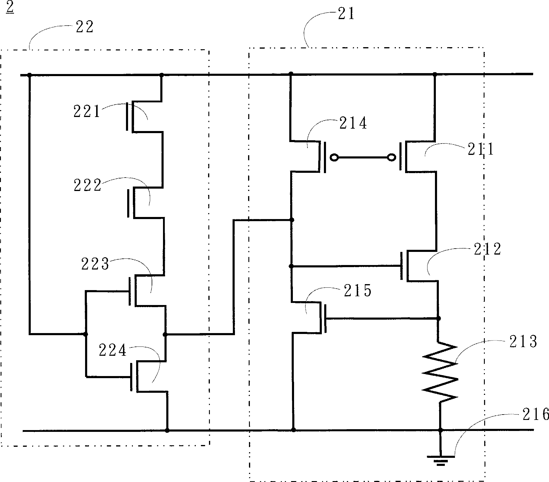
[0019] see figure 2 , figure 2 It is a current source stabilization circuit structural diagram of a preferred embodiment of the present invention, as figure 2 As shown, the current source stabilization circuit 2 includes a current source circuit 21 and a correction circuit 22, the current source circuit 21 includes a first PMOS (P-type metal oxide semiconductor) 211, a first NMOS (N-type metal oxide semiconductor) 212 , a first resistor 213 , a second PMOS 214 , a second NMOS 215 and a ground terminal 216 .

[0020] The correction circuit 22 includes a third NMOS 221 , a fourth NMOS 222 , a fifth NMOS 223 and a sixth NMOS 224 .

[0021] The source of the first PMOS 211 is coupled to the sources of the second PMOS 214 and the third NMOS 221 , the gate is coupled to the gate of the second PMOS 214 , and the drain is coupled to the source of the first NMOS 212 . The gate of the first NMOS212 is coupled to the drain of the second PMOS214 and the source of the second NMOS215,...


PUM


Abstract

The invention relates to a current source stabilizing circuit which is used for stabilizing a current value output by a current source under the condition that temperature is changed. The current value of the current source can rise with the rising of temperature. The current source stabilizing circuit comprises a current source circuit used for providing current which rises with the rising of temperature, a correction circuit which is coupled with the current source circuit and used for providing input current which rises with the rising of temperature; wherein, the current of the current source circuit becomes the current of the current source after being subtracted by the input current; the current of the current source does not change with the temperature. The current source stabilizing circuit can effectively save cost and the space of hardware.

Description

technical field [0001] The present invention relates to a current source stabilizing circuit, in particular to a current source stabilizing circuit used for stabilizing a current source whose current increases with temperature. Background technique [0002] In the design of integrated circuits, some reference voltages and reference currents are often required, and the reference voltages and reference currents are usually included in the bias voltage part of the entire integrated circuit. In general applications, these bias voltages are usually designed based on the operating temperature of the circuit, without special consideration of the relationship with temperature changes. [0003] However, in fact, when the circuit is working, the temperature of the circuit is often changed due to the change of the ambient temperature or the heat generated by the electronic components in the circuit. The temperature change may affect the circuit application when the signal is converted,...

Claims


Application Information

Patent Timeline
Patent Type & Authority Applications(China)
IPC IPC(8): G05F1/567
Inventor 詹勋典
Owner PRINCETON TECHNOLOGY
Why Eureka
Try Eureka