Refrigeration device

A refrigeration device and refrigerant technology, used in refrigerators, refrigeration components, refrigeration and liquefaction, etc., can solve the problems of refrigerant pressure drop, inability to gasify refrigerant at intermediate pressure, and refrigerant temperature drop.

Inactive Publication Date: 2009-03-11
DAIKIN IND LTD
View PDF1 Cites 8 Cited by
  • Summary
  • Abstract
  • Description
  • Claims
  • Application Information

AI Technical Summary

Problems solved by technology

However, if the intermediate pressure heat exchanger is far away from the heat exchanger on the use side, or if the intermediate pressure heat exchanger is placed at a higher position than the heat exchanger on the use side, it may happen that the heat from the use side in the pipeline The pressure of the refrigerant drops during the flow from the exchanger to the intermediate pressure heat exchanger, so that part of the refrigerant evaporates and the temperature of the refrigerant decreases
As a result, the temperature difference between the high-pressure refrigerant and the intermediate-pressure refrigerant that exchange heat with each other in the intermediate-pressure heat exchanger decreases, and the intermediate-pressure refrigerant may not be reliably vaporized in the intermediate-pressure heat exchanger.

Method used


Image

  • Refrigeration device
  • Refrigeration device
  • Refrigeration device

Examples


Embodiment approach 1

Embodiment 1 of the present invention will be described. The present embodiment relates to an air conditioner 10 constituted by the refrigeration device of the present invention.

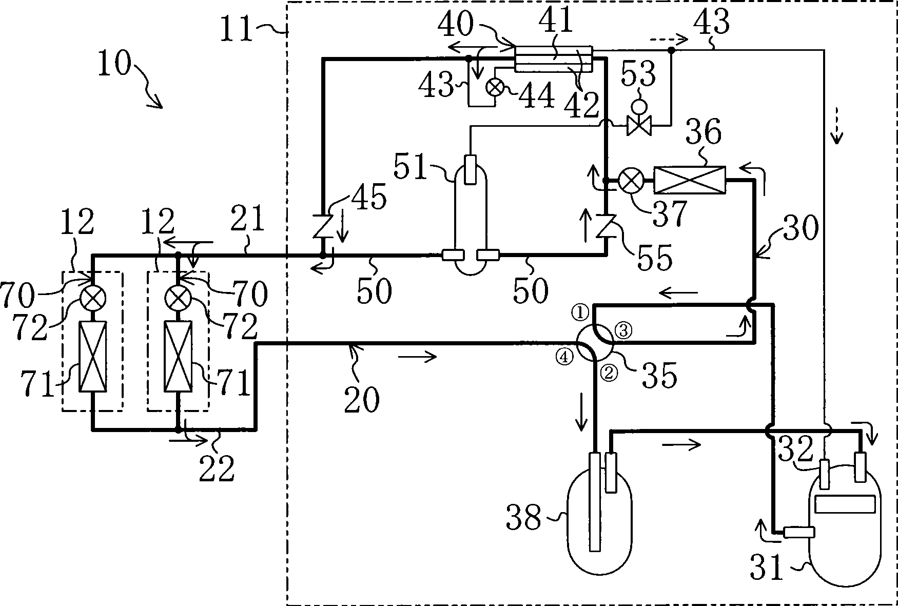
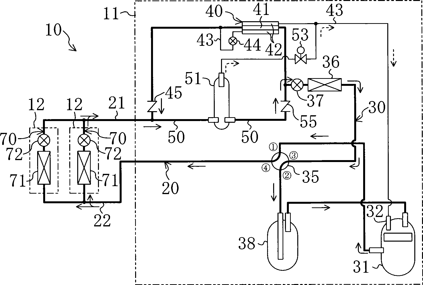
[0031] As shown in FIG. 1 , the air conditioner 10 of this embodiment has one outdoor unit 11 and two indoor units 12 . In addition, the number of indoor units 12 is merely an example. An outdoor circuit 30 serving as a heat source side circuit 30 is accommodated in the outdoor unit 11 . Each indoor unit 12 accommodates an indoor circuit 70 as a use-side circuit.

[0032] In the air conditioner 10 , the refrigerant circuit 20 is formed by connecting the outdoor circuit 30 and the indoor circuit 70 with the liquid-side connecting pipe 21 and the gas-side connecting pipe 22 . In this refrigerant circuit 20 , two indoor circuits 70 are connected in parallel to one outdoor circuit 30 .

[0033] Each of the indoor circuits 70 is provided with one indoor heat exchanger 71 as a usage-side heat exchanger...

Embodiment approach 2

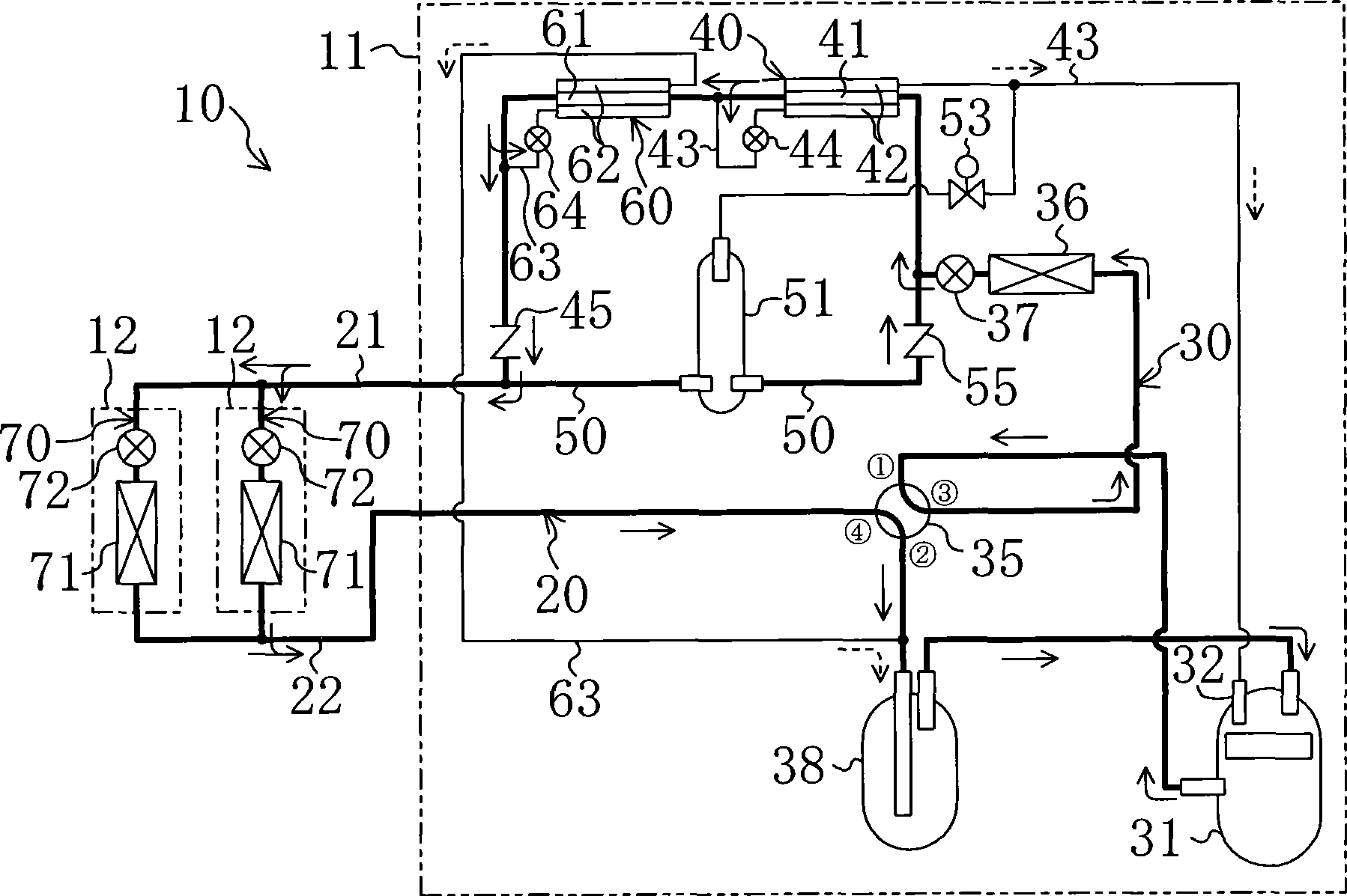
Embodiment 2 of the present invention will be described. This embodiment is an example in which a subcooling heat exchanger 60 and a supercooling duct 63 are added to the air conditioner 10 of the first embodiment. Here, differences between the air conditioner 10 of the present embodiment and the first embodiment described above will be described.

[0060] As shown in FIG. 2 , a subcooling heat exchanger 60 is provided in the outdoor circuit 30 . The subcooling heat exchanger 60 is a heat exchanger for exchanging heat between refrigerants in a jacket heat exchanger, a plate heat exchanger, and the like. A first flow path 61 and a second flow path 62 are formed in the subcooling heat exchanger 60 . The first flow path 61 of the subcooling heat exchanger 60 is provided between the intermediate pressure heat exchanger 40 and the first check valve 45 in the outdoor circuit 30 .

[0061] The start end of the supercooling pipe 63 is connected between the subcooling heat exchanger ...


PUM


Abstract

A refrigeration device (20) has an intermediate-pressure heat exchanger (40) and a gas-liquid separator (51). In cooling operation, that portion of refrigerant which is condensed in an outdoor heat exchanger (36) flows into injection piping (43). The pressure of the refrigerant flowed into the injection piping (43) is reduced to an intermediate pressure when the refrigerant passes an injection expansion valve (44), and then the refrigerant is supplied to an intermediate pressure port (32) of a compressor (31) after evaporating at the intermediate- pressure heat exchanger (40). In heating operation, the pressure of the refrigerant condensed at an indoor heat exchanger (71) is reduced to an intermediate pressure when the refrigerant passes an indoor expansion valve (72), and then the refrigerant flows into the gas-liquid separator (51). The intermediate-pressure gas refrigerant in the gas-liquid separator (51) is supplied to the intermediate pressure port (32) of the compressor (31).

Description

technical field [0001] The present invention relates to a refrigerating device that supplies an intermediate-pressure gaseous refrigerant to a compressor, that is, performs gas injection. Background technique [0002] Conventionally, refrigerating apparatuses that perform so-called gas injection (that is, the operation of supplying intermediate-pressure gaseous refrigerant to the compressor) for the purpose of reducing the input power of the compressor are known. For example, FIG. 1 of Patent Document 1 discloses an example of supplying an intermediate-pressure gaseous refrigerant to a compression chamber of a compressor in a compression process in a refrigeration apparatus performing a single-stage compression refrigeration cycle. Also, FIG. 13 of Patent Document 1 discloses an example in which an intermediate-pressure gaseous refrigerant is supplied between a low-stage compressor and a high-stage compressor in a refrigeration system performing a two-stage compression refri...

Claims


Application Information

Patent Timeline
Patent Type & Authority Applications(China)
IPC IPC(8): F25B1/00F25B1/10F25B13/00
CPCF25B2400/23F25B2400/13F25B13/00F25B2400/05F25B1/10F25B2400/053F25B2313/02741F25B2500/01F25B1/00
Inventor 山田昌弘山口贵弘
Owner DAIKIN IND LTD
Why Eureka
Try Eureka