Microfluidic cell culture device and method for using same

a microfluidic cell culture and cell technology, applied in the field of microfluidic cell culture devices, can solve the problems of pdms based microfluidic chips, evaporation, cell death, etc., and achieve the effects of preventing undesirable shifts in the osmolality of the fluid, preventing evaporation of the fluid contained, and ensuring mechanical durability and stability

Inactive Publication Date: 2007-04-19
RGT UNIV OF MICHIGAN
View PDF12 Cites 42 Cited by
  • Summary
  • Abstract
  • Description
  • Claims
  • Application Information

AI Technical Summary

Benefits of technology

[0011] Embodiments of the invention may take the form of a microfluidic cell culture device. The device includes a substrate and a passage formed in the substrate. The device also includes a multilayer membrane having upper and lower surfaces. The upper surface partially defining a portion of the passage and the membrane being locally deformable upon actuation of the membrane at the lower surface of the membrane so that at least one localized portion of an upper layer of the membrane extends into the passage. One layer of the membrane minimizes evaporation of fluid contained within the passage to prevent undesirable shifts in osmolality of the fluid, is resistant to the flow of at least one gas from the passage, and provides mechanical durability and stability against cracking caused by locally deforming the membrane through the actuation at the lower surface of the lower layer of the membrane.
[0027] Embodiments of the invention may take the form of a method for controlling the flow of a biological fluid in a microfluidic cell culture device. The method includes providing a substrate, a passage formed in the substrate, and a multilayer membrane having upper and lower surfaces. The upper surface at least partially defines a portion of the passage. The method also includes adding a biological fluid into the passage and locally deforming the membrane through actuation of the lower surface of the membrane so that at least one localized portion of an upper layer of the membrane extends into the passage to control the movement of at least a portion of the biological fluid in the passage. One layer of the membrane minimizes evaporation of the biological fluid contained within the passage to prevent undesirable shifts in osmolality of the biological fluid, is resistant to the flow of at least one gas from the passage, and provides mechanical durability and stability against cracking caused by locally deforming the membrane through actuation at the lower surface of the lower layer of the membrane.

Problems solved by technology

A challenge with PDMS based microfluidic chips, however, is evaporation.
Evaporation is especially detrimental to cell culture in microfluidic chips as even the slightest evaporation from small liquid volumes present may result in significant increases in osmolality.
Devices with thin PDMS layers may thus experience osmolality shifts that result in cell death.
Although useful and beneficial for many applications, these methods also have drawbacks and limitations such as limiting the environment that the chip can be used in, altering optical access, and hindering the interface to external devices such as Braille display-based microactuator arrays.
Although parylene has been coated onto PDMS previously, there was little consideration for support of cell growth and viability, mechanical stability, or ability to perform optical microscopy.
For example, if parylene is coated on the outside of a PDMS membrane and subjected to deformation-based fluid actuation using piezoelectric pin actuators of a refreshable Braille display, the parylene membrane will become scratched, scarred, and cracked thus affecting its permeability relative to water.

Method used


Image

  • Microfluidic cell culture device and method for using same
  • Microfluidic cell culture device and method for using same
  • Microfluidic cell culture device and method for using same

Examples


Embodiment Construction

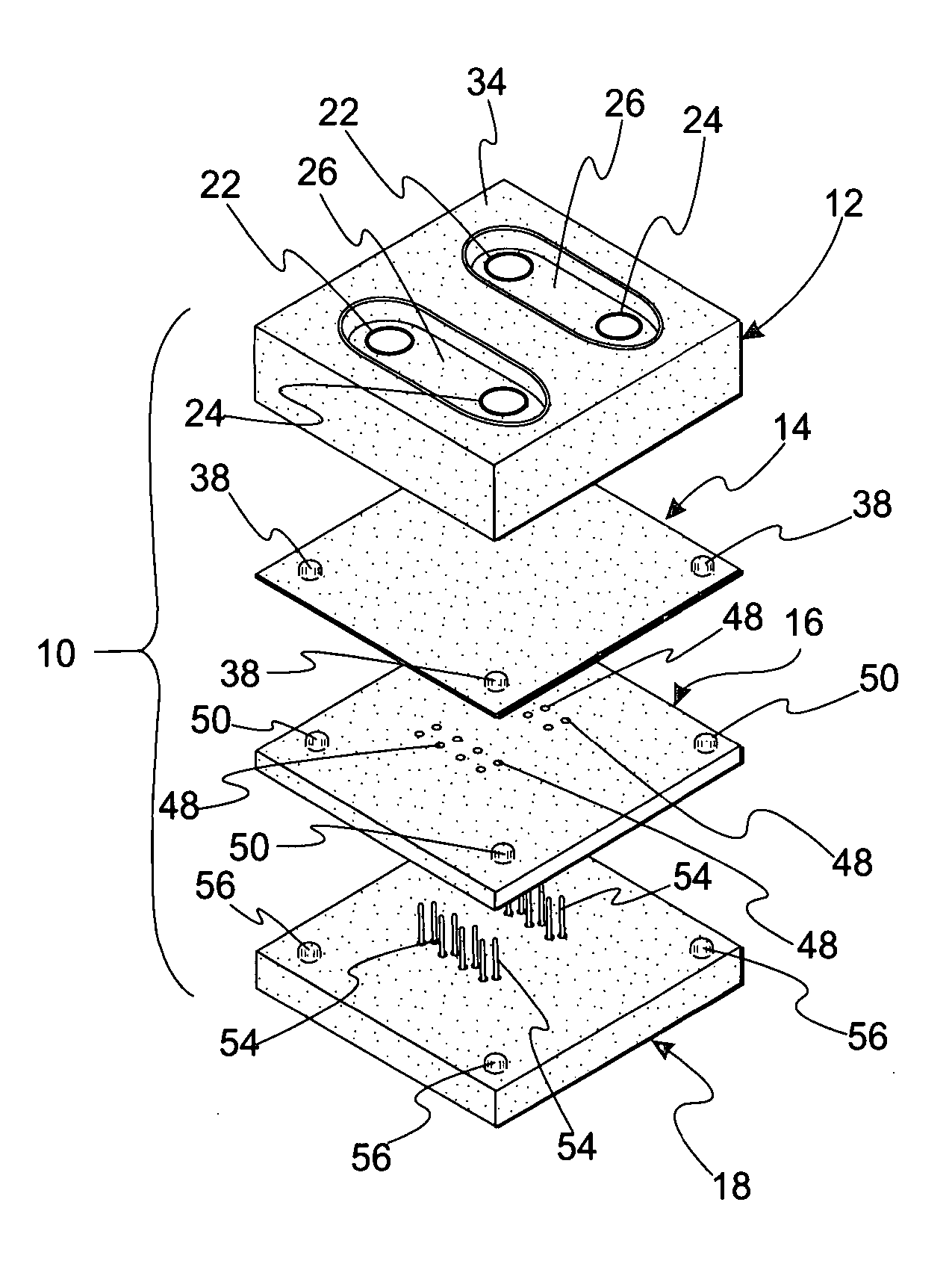
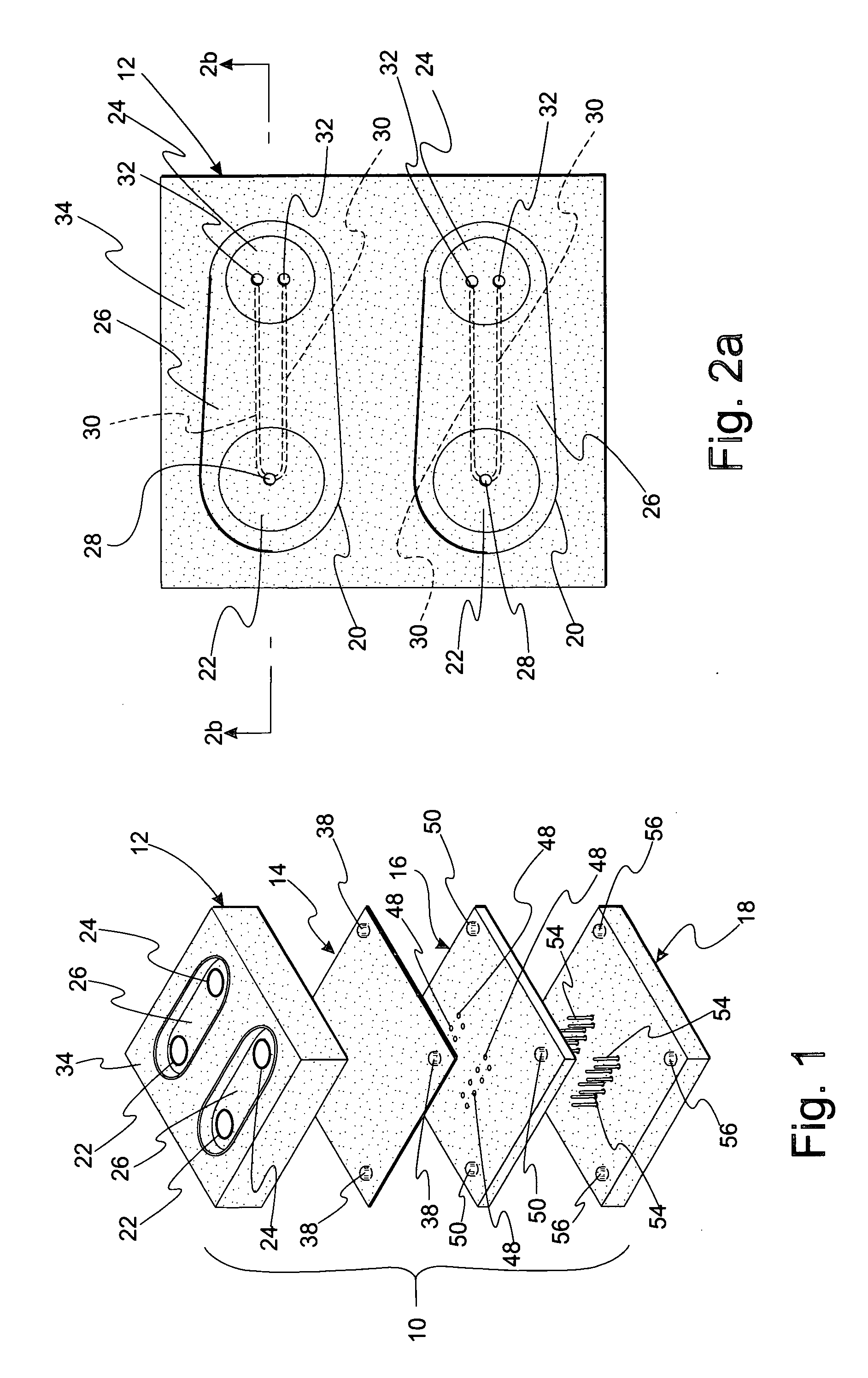
[0043]FIG. 1 is an exploded, perspective view of microfluidic cell culture system or device 10. Device 10 includes substrate 12 configured to receive a cellular mass, e.g., an embryo, as explained in detail below, non-rigid membrane 14, locating block 16, and pin actuating device 18.

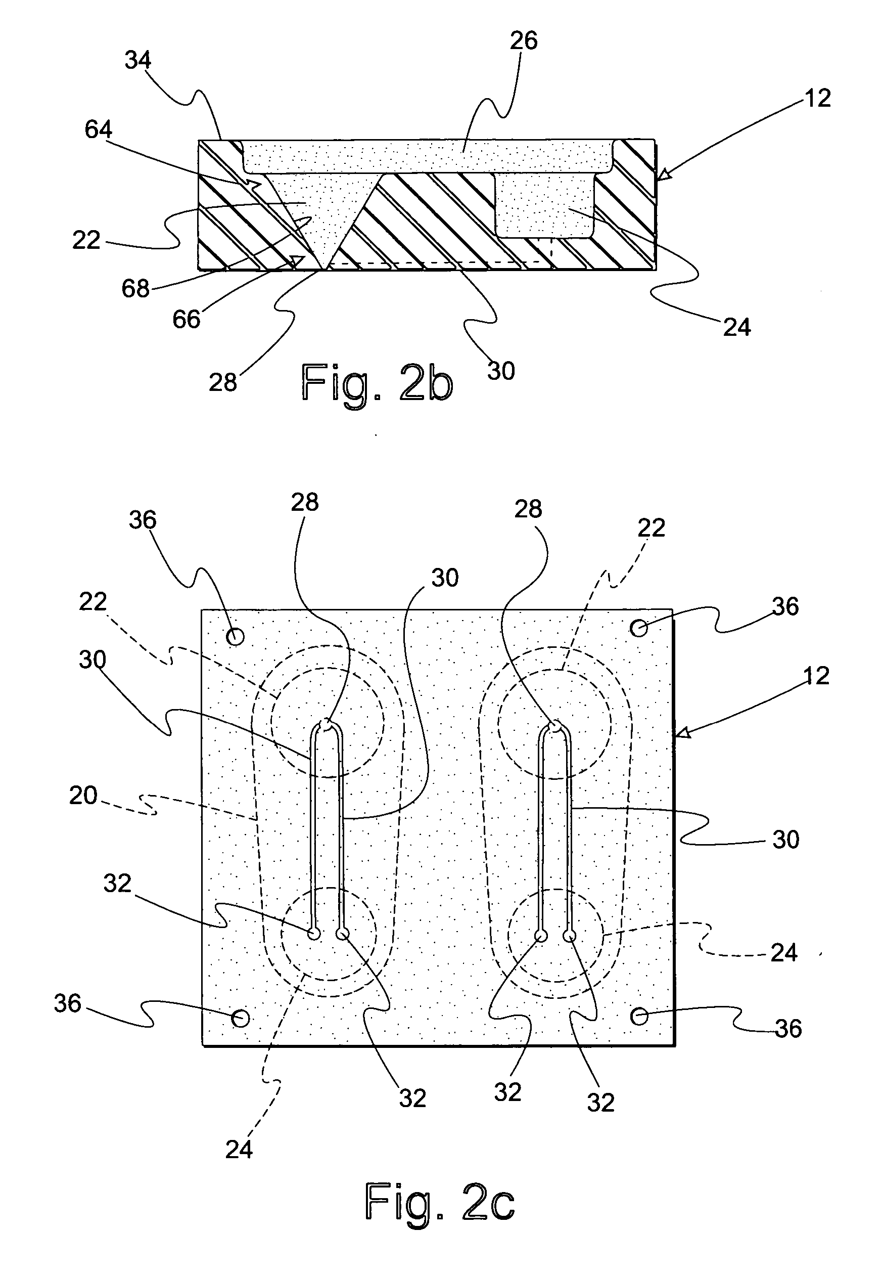
[0044]FIG. 2a is a top view of substrate 12. Substrate 12 includes funnel 22, reservoir 24, and overlay reservoir 26. Bottom portion 28 of funnel 22 is in fluid communication with reservoir 24 via microchannel 30. Microchannel 30 has a volume less than 1 microliter. Reservoir 24 includes reservoir openings 32 which provide openings to microchannel 30 such that fluids may travel between funnel 22 and reservoir 24 as explained in detail below.

[0045]FIG. 2b is a side view, and in cross-section, of substrate 12 taken along section line 2b-2b in FIG. 2a. A portion of microchannel 30 is formed in substrate 12 while another portion of microchannel 30 is formed by membrane 14 as described in detail below. Micr...


PUM


Abstract

Microfluidic devices for cell culturing and methods for using the same are disclosed. One device includes a substrate and membrane. The substrate includes a reservoir in fluid communication with a passage. A bio-compatible fluid may be added to the reservoir and passage. The reservoir is configured to receive and retain at least a portion of a cell mass. The membrane acts as a barrier to evaporation of the bio-compatible fluid from the passage. A cover fluid may be added to cover the bio-compatible fluid to prevent evaporation of the bio-compatible fluid.

Description

CROSS-REFERENCE TO RELATED APPLICATIONS [0001] This application claims the benefit of the following U.S. provisional applications: Ser. No. 60 / 727,934 filed Oct. 18, 2005; Ser. No. 60 / 728,030, filed Oct. 18, 2005; Ser. No. 60 / 741,665, filed Dec. 2, 2005; Ser. No. 60 / 741,864, filed Dec. 2, 2005; Ser. No. 60 / 802,705, filed May 23, 2006; and Ser. No. 60 / 812,166, filed Jun. 9, 2006.STATEMENT REGARDING FEDERALLY SPONSORED RESEARCH OR DEVELOPMENT [0002] This invention was made with Government support under at least one of: Contract No. F012482; Contract No. F008090; Contract No. N006624; Grant No. HD049607-01 awarded by National Institute of Health; Contract / Grant No. DAAD19-03-1-0168 awarded by the U.S. Army Research Laboratory and the U.S. Army Research Office; BES-0238625 awarded by the National Science Foundation; NNC04AA21A awarded by the NASA BioScience and Engineering Institute; and USDA 2005-35203-16148 awarded by the United States Department of Agriculture. The Government has cer...

Claims


Application Information

Patent Timeline
Patent Type & Authority Applications(United States)
IPC IPC(8): H01H29/00C12N5/07C12N5/071
CPCB01L3/502738B01L2200/142B01L2300/0816B01L2300/0887B01L2400/0481B01L2400/0655C12M23/16C12M23/34
Inventor TAKAYAMA, SHUICHICABRERA, LOURDES MARCELLAFUTAI, NOBUYUKIHEO, YUN SEOKSMITH, GARY DANIEL
Owner RGT UNIV OF MICHIGAN
Why Eureka
Try Eureka