A method of deriving a graphical representation of domain-specific display objects on an external display

A technology for displaying objects and specific areas, applied in the direction of digital output to display devices, applications, sensors, etc., can solve different problems, and achieve the effect of low hardware requirements and low bandwidth requirements

Active Publication Date: 2009-03-11
KONINKLIJKE PHILIPS ELECTRONICS NV
View PDF1 Cites 4 Cited by
  • Summary
  • Abstract
  • Description
  • Claims
  • Application Information

AI Technical Summary

Problems solved by technology

The disadvantage of this method is that the control of monitor functions (e.g., alarm lim

Method used


Image

  • A method of deriving a graphical representation of domain-specific display objects on an external display

Examples


Embodiment Construction

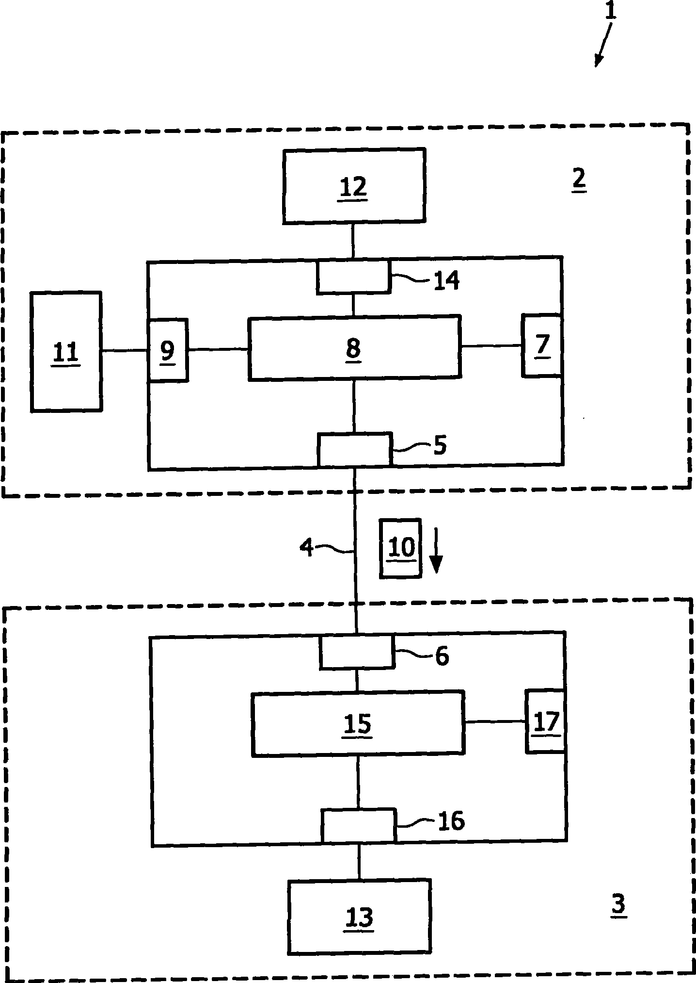
[0018] By referring to the following examples and figure 1 With reference to the accompanying drawings, these and other aspects of the invention are described in detail below by way of example, figure 1 A patient monitoring system is schematically illustrated.

[0019] A patient monitoring system 1 according to the invention comprises a patient monitor 2 and an external display device 3 which can be connected to the patient monitor 2 via a LAN communication link 4 . For this purpose, the patient monitor 2 includes a LAN-compatible system interface 5 and the external display device 3 includes a LAN interface 6 . Connect all components of patient monitor 2 to power supply 7.

[0020] The patient monitor 2 includes a processing unit (CPU) 8 in which display manager software is executed; thus, the CPU 8 functions as a first display management device. The monitoring data (measurement data) is processed by the CPU 8 via the display manager software, which is transmitted from the ...


PUM


Abstract

In order to provide a technique for deriving a graphical representation of domain-specific display objects on an external display (13) within a patient-monitoring system (1), only a small amount of data has to be transmitted to the external display device (3) and at the same time the user of the external display (13) gets the same 'look and feel' as he is used to from the built-in display (12) of a patient monitor (2).

Description

technical field [0001] The present invention relates to a method of obtaining a graphical representation of an area-specific display object on an external display within a patient monitoring system. Furthermore, the invention relates to a patient monitoring system and to a computer program for display management in such a patient monitoring system. Background technique [0002] Patient monitors are used in medical environments where a patient's heart function, respiration, etc. are monitored. Sometimes a patient monitor's built-in display is not large enough to show all the information a physician or nurse needs. In this case, a second external display can be connected to the patient monitor. [0003] Two methods are known to control such external displays. First, the remote graphical interface method can be used. In this case, the complete graphics data and user input are transmitted to the external display. Examples of this approach are the UNIX-based "X-Windows" or t...

Claims


Application Information

Patent Timeline
IPC IPC(8): G06F3/14A61B5/00
CPCA61B5/0013A61B5/0002G06F19/3406G06F19/3418G16H40/63
Inventor H·格赖纳U·泰瑟尔K·哈辛
Owner KONINKLIJKE PHILIPS ELECTRONICS NV
Why Eureka
Try Eureka