Method and device for lubricating a tool and workpiece when cutting

A blanking, workpiece technology, used in maintenance and safety accessories, metal processing machinery parts, forming tools, etc., can solve problems such as the inability to ensure that lubricants can enter the forming area, and achieve high process reliability/safety and service life. Long, highly repeatable effects

Inactive Publication Date: 2009-03-18
FEINTOOL INTPROP
View PDF1 Cites 19 Cited by
  • Summary
  • Abstract
  • Description
  • Claims
  • Application Information

AI Technical Summary

Problems solved by technology

This known solution does not ensure lubricant access to the forming zone

Method used


Image

  • Method and device for lubricating a tool and workpiece when cutting
  • Method and device for lubricating a tool and workpiece when cutting
  • Method and device for lubricating a tool and workpiece when cutting

Examples


Embodiment 1

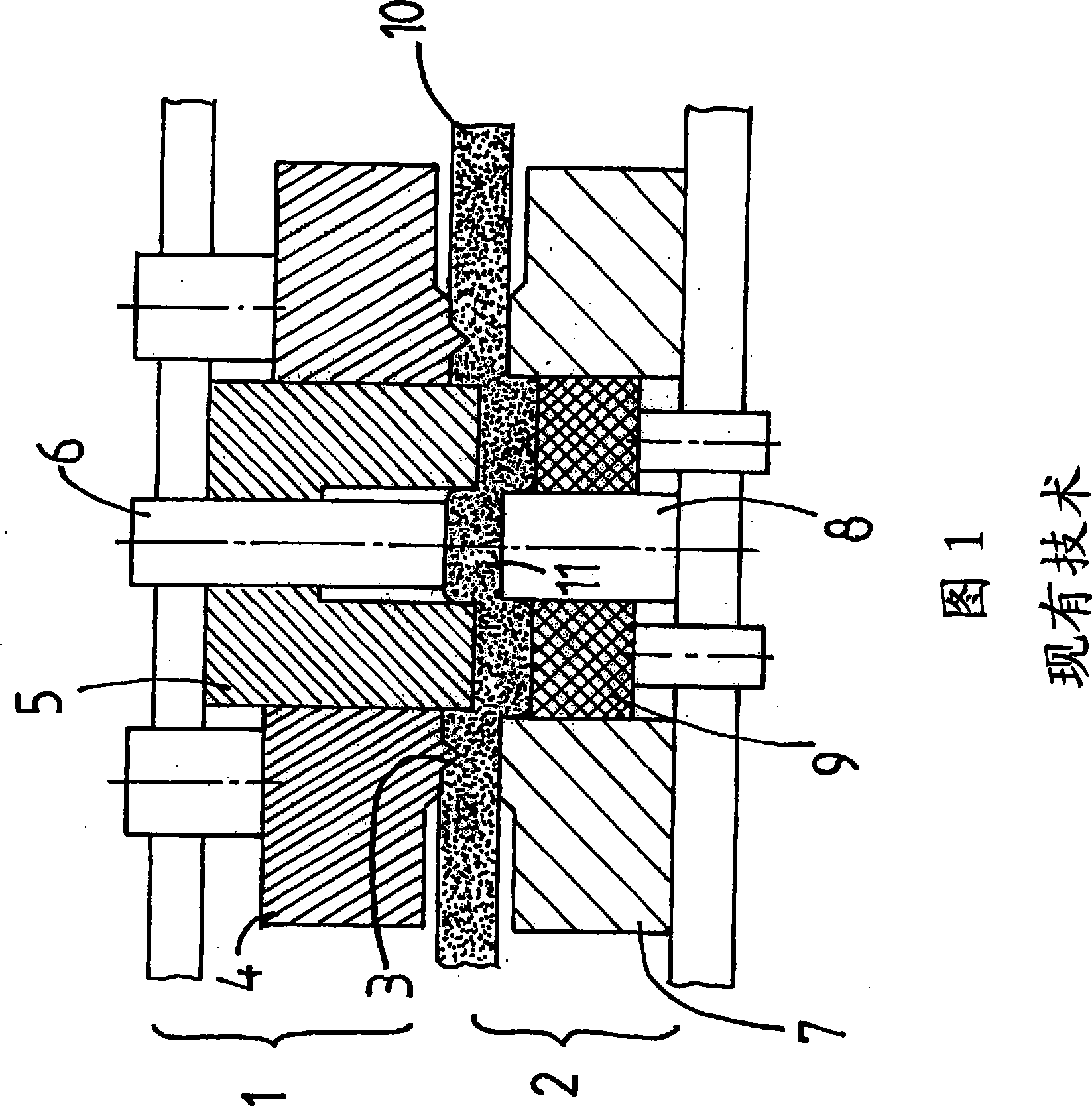
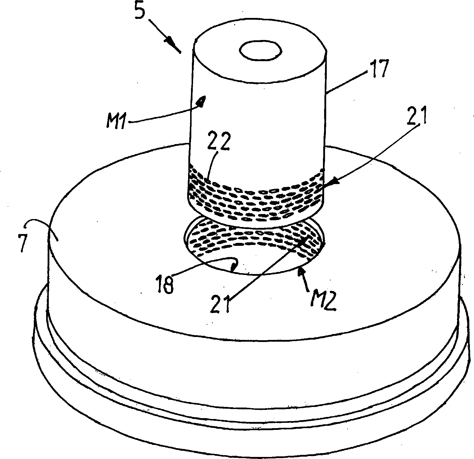
[0044] The device according to the invention in Example 1 has essentially the same structure as the device described with reference to FIG. 1 . image 3 The microsurface structure 21 according to the invention is shown on the example of the functional surfaces 17 and 18 of the punch punch 5 and the punch die 7 . The outer surface M1 of the punch punch 5 and the outer surface M2 of the punch die 7 are polished and coated with, for example, titanium carbonitride (Titankarbonitrid). A plurality of recesses 22 formed by laser machining or other suitable machining methods (such as grinding, milling, etc.) cover the outer surfaces M1 and M2. The average depth of the depressions 22 is about 0.05mm. The depressions 22 are distributed in regular, mutually spaced horizontal rows which are arranged perpendicular to the punching direction SR. The depressions cover the functional surfaces 17 and 18 evenly.

[0045] The depressions 22 can have different geometries (sizes) and shapes. Thu...

Embodiment 2

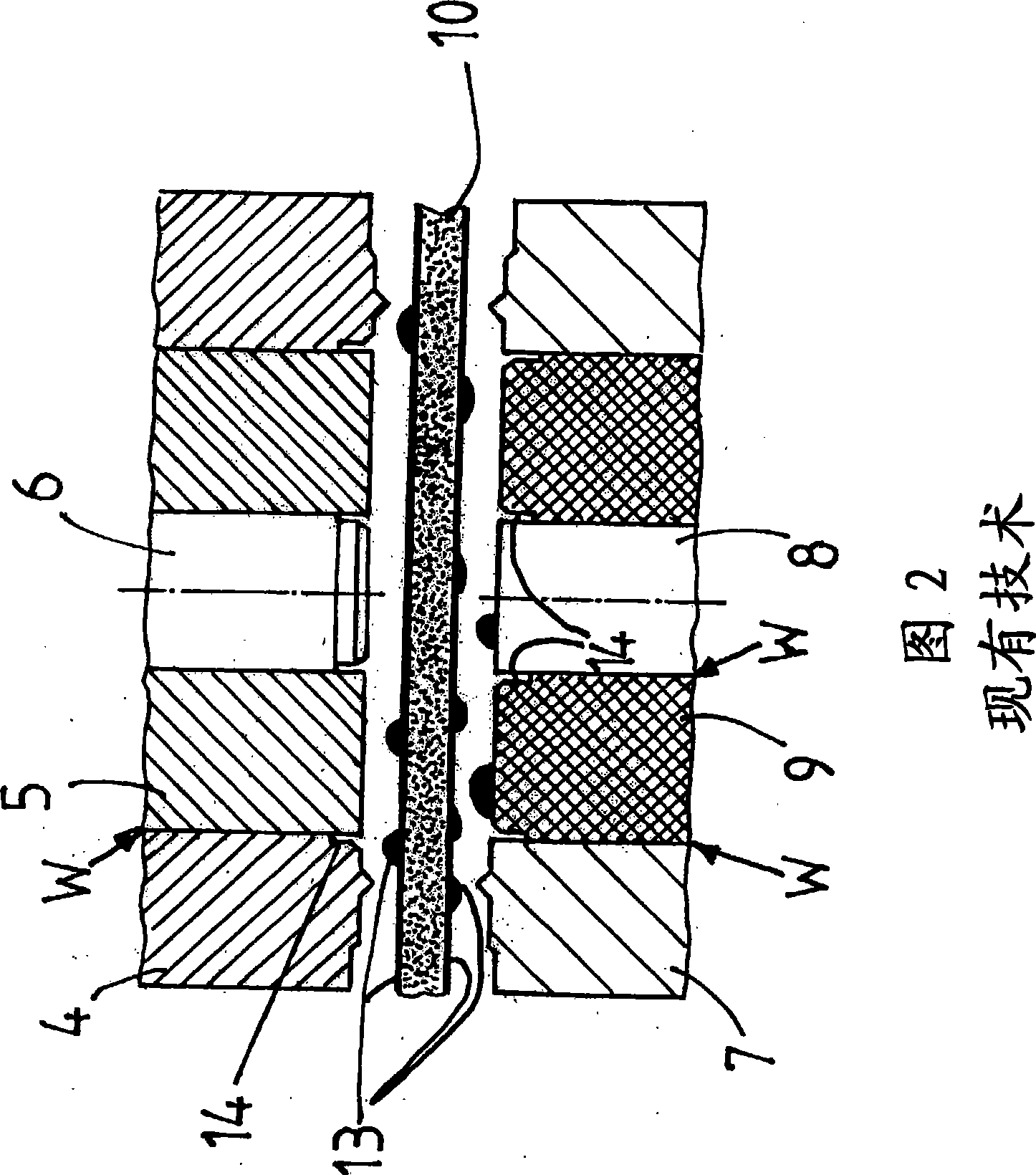
[0056] FIGS. 6-8 show another variant of the device according to the invention, which is identical in basic structure to that of the mold shown in FIG. 1 . In addition to the oil chamber 14 on the guide plate 4 and the ejector 9, the guide plate 4, the ejector 9 and the pusher 6 also have channels 23 for passing between the guide plate 4 and the blanking punch 5. , punching punch 5 and pusher 6 and between punching die 7 and ejector 9 are used to feed additional punching oil 13 into the corresponding microstructure. The channel 23 is connected to a supply line (not shown) for connection to a pressure pump for setting the pressure of the punching oil 13 to be supplied. The channel 23 extending in the punching direction SR in the guide plate 4, the ejector 9 and the pusher 6 transitions into a region 24 extending perpendicularly to the punching direction with an opening 25 widening towards the active seam, which is maintained continuously. The punching oil 13 under pressure can...


PUM

PropertyMeasurementUnit
depthaaaaaaaaaa
depthaaaaaaaaaa

Abstract

The invention relates to a method and a device for lubricating tool and workpiece at cutting and forming, especially fine blanking of a workpiece with a thickness of 5 mm or more and with complex part geometry from a flat strip. The invention has the task to further develop a method and a device for lubricating a tool and a workpiece at cutting and forming, especially at fine blanking of workpieces, so that fine blanking of thicker parts is reproducible controlled process secure with high quality and at the same time extended edge life of the tools by lubricating the active surfaces up to the forming zone without the provided lubricating film breaking off. This task is solved in the manner that from the stocked up cutting oil one quantity is accumulated in a micro-surface structure of a functional surface of shearing punch and cutting die and evenly distributed on the functional surfaces as quasi-stationary cutting oil film by cooperation of moving past each other functional surfaces, when the tool is closed, and that one quantity of accumulated cutting oil via the respective effective gaps is provided to the active surfaces of shearing punch and workpiece in the forming zone.

Description

technical field [0001] The invention relates to a method for lubricating dies and workpieces when punching and forming workpieces with a thickness starting from 5 mm and partly geometrically complex, in particular when fine-blanking workpieces from strips, in which method there is sufficient wetting on the surface side The strip of thick blanking oil film is clamped between the upper part and the lower part when closing, said upper part is formed by the punching punch, the guide plate for the punching punch, the teeth arranged on the guide plate Composed of ring and pusher, the lower part includes blanking die, ejector and inner contour punch, punching oil / cutting fluid passes through guide plate, punching die, pusher, punching die , the ejector and the inner contour punch are extruded, squeezed into the lubricating oil cavity formed by the chamfer formed on the guide plate, the pusher and the ejector, and temporarily stored in the cavity. [0002] The invention also relates ...

Claims


Application Information

Patent Timeline
Patent Type & Authority Applications(China)
IPC IPC(8): B21D37/18B21D28/14
CPCB21D28/16B21D37/18Y10T409/304032B23Q11/121B23Q11/10
Inventor U·施拉特
Owner FEINTOOL INTPROP
Why Eureka
Try Eureka