
Machine element for a shaft-to-hub connection and production method for a shaft-to-hub connection

A technology for mechanical components and connecting devices, applied in the direction of connections, mechanical equipment, couplings, etc., can solve the problems of damage to mechanical components, high clamping force, and limitation of coaxiality accuracy.

Inactive Publication Date: 2009-03-18
GM GLOBAL TECH OPERATIONS LLC
View PDF1 Cites 2 Cited by
  • Summary
  • Abstract
  • Description
  • Claims
  • Application Information

AI Technical Summary

Problems solved by technology

However, concentricity accuracy is limited
In addition, particularly with small shaft diameters, high clamping forces can occur due to the clamping, which can cause damage to the machine element with the hub

Method used


Image

  • Machine element for a shaft-to-hub connection and production method for a shaft-to-hub connection
  • Machine element for a shaft-to-hub connection and production method for a shaft-to-hub connection
  • Machine element for a shaft-to-hub connection and production method for a shaft-to-hub connection

Examples


Embodiment Construction

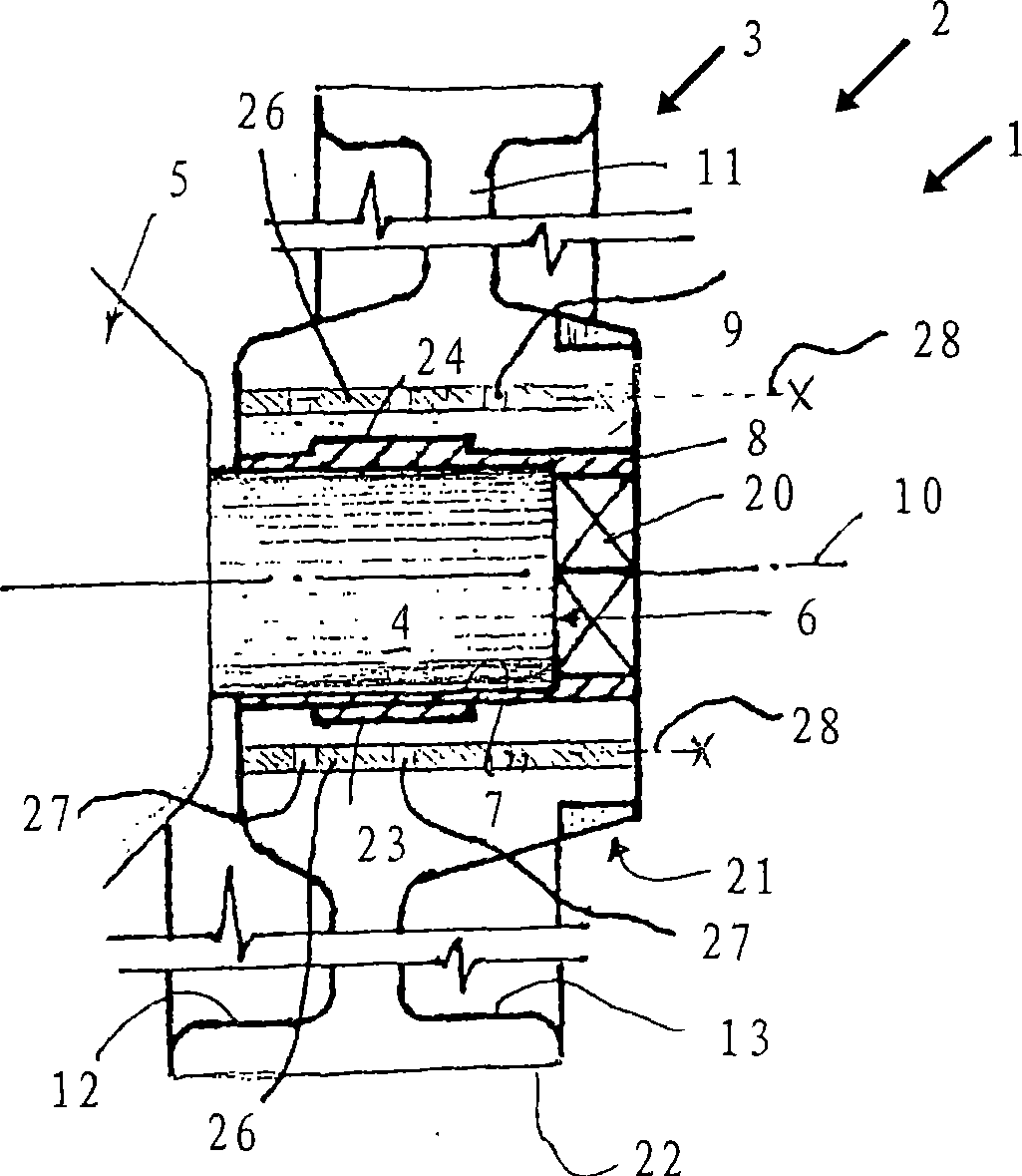
[0032] figure 1 A shaft-hub-connection 1 between a machine element 2 in the form of a pulley 3 and a shaft 4 or shaft end is shown. The shaft 4 is used to drive a vehicle assembly 5 , not further shown. However, the shaft-hub connection can also be used to connect other machine elements and shafts at other points.

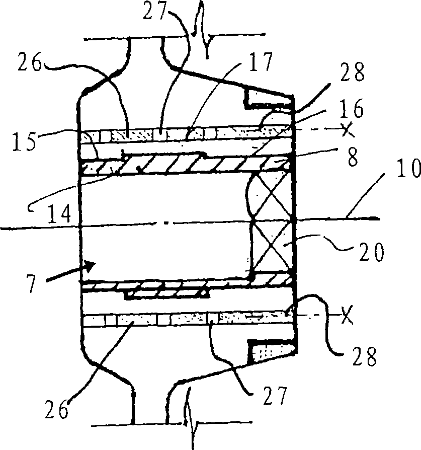
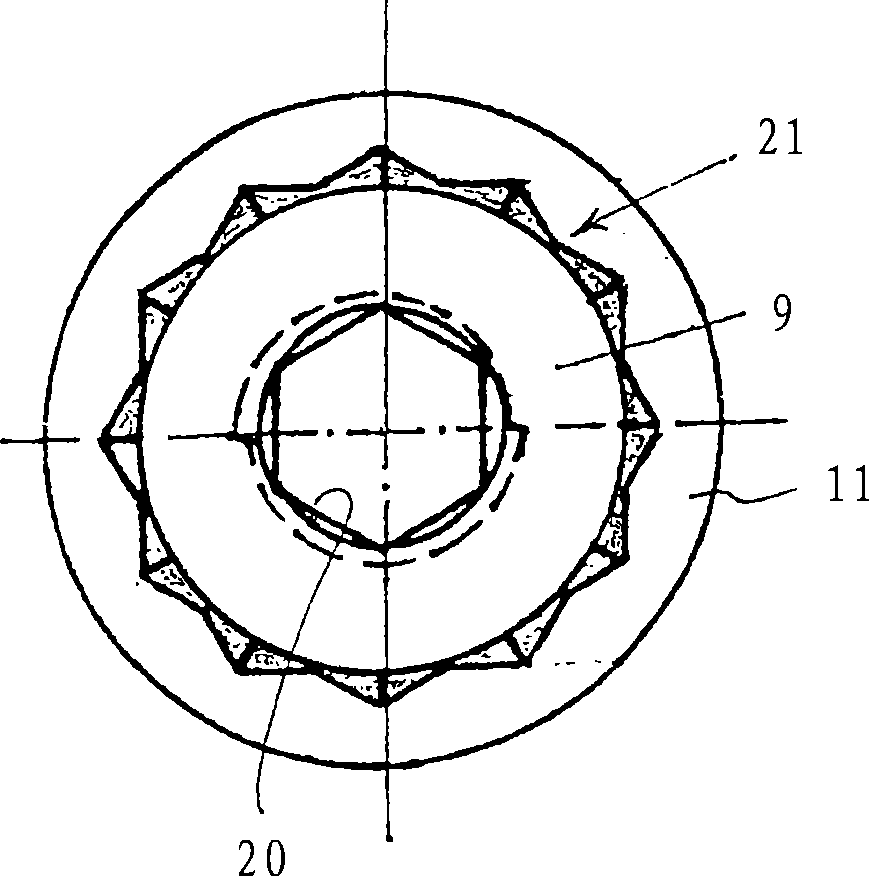
[0033] The shaft end 4 is substantially cylindrical. It has a preferably substantially flat end face 6 which is seated in the opening of a bore 7 in the form of a clamping element 8 which is arranged in a hub 9 of the belt pulley 3 . The clamping element 8 and thus the bore 7 are oriented concentrically to the axis of rotation 10 , which coincides with the axis of rotation of the shaft 4 .

[0034] The belt pulley 3 has a support sleeve 26 by means of which the forces and clamping forces occurring in the belt pulley 3 can be absorbed, so that the belt pulley 3 can withstand significantly greater forces from the clamping than without the support sleeve 26. compo...


PUM

PropertyMeasurementUnit
Average roughnessaaaaaaaaaa

Abstract

The invention relates to a machine element (2) used for a shaft-to-hub connection (1), containing an un-notched tensioning / clamping element (8), which is inserted into a receptacle space of the machine element (2). The tensioning / clamping element (8) has an opening (7) for receiving a shaft (4) twistable relative to the machine element (2), a supporting sleeve (26) arranged radially external to the tensioning / clamping element (8). Therefore, the machine element (2) has the advantages of easy manufacture, excellent use and bearing large force.

Description

technical field [0001] The invention relates to a machine element for a shaft-hub connection, which connects a rotating or stationary machine element to a shaft in a rotationally fixed manner by means of an eccentric clamping sleeve, and to a corresponding production method. Background technique [0002] The establishment of a torsion-resistant connection between rotating or stationary mechanical elements, such as a shaft that rotates continuously or alternately back and forth, and mechanical elements fixed thereto, such as levers, pulleys, cams, gears and similar parts, proposed in the past Quite a few different arrangements. For example DE 4327461 A1 discloses a device which, by means of an eccentric fastening device, connects a shaft in a rotationally fixed manner to an outer six-sided mechanical part. This is the case for slotted sleeves with a wedge-shaped profile on the outside, wherein the sleeve is rotatable relative to the outer machine element and thus clamped bet...

Claims


Application Information

Patent Timeline
IPC IPC(8): F16D1/06
CPCY10T403/7011Y10T29/49826F16D1/0817F16D1/0835Y10T403/7061Y10T403/7051Y10T403/10
Inventor 厄茨·克里施克
Owner GM GLOBAL TECH OPERATIONS LLC
Learn More