
Laser processing device adopting pseudo-coaxial visual system

A vision system and laser processing technology, used in laser welding equipment, metal processing equipment, manufacturing tools, etc., can solve the problems of increasing processing costs and production cycles, and achieve the effects of good versatility, accurate positioning, and fast response speed.

Pending Publication Date: 2021-12-07
广东国玉科技股份有限公司
View PDF8 Cites 0 Cited by
  • Summary
  • Abstract
  • Description
  • Claims
  • Application Information

AI Technical Summary

Problems solved by technology

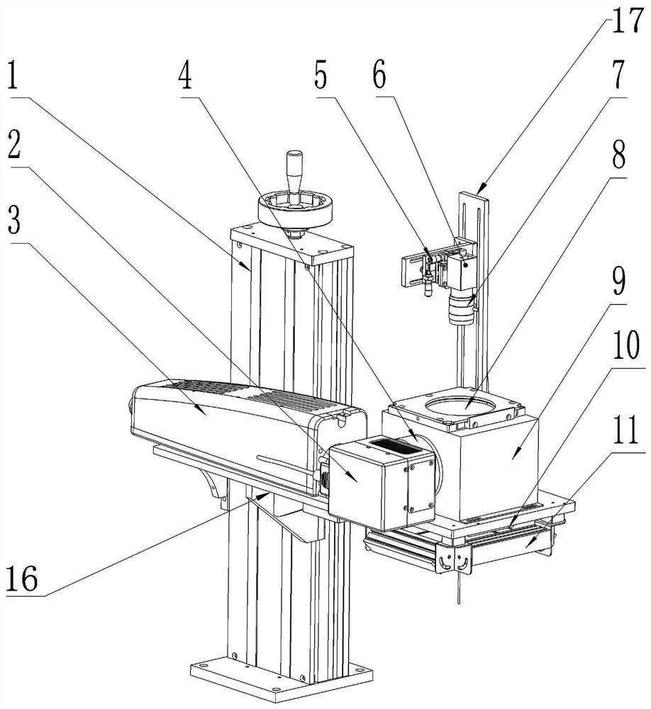
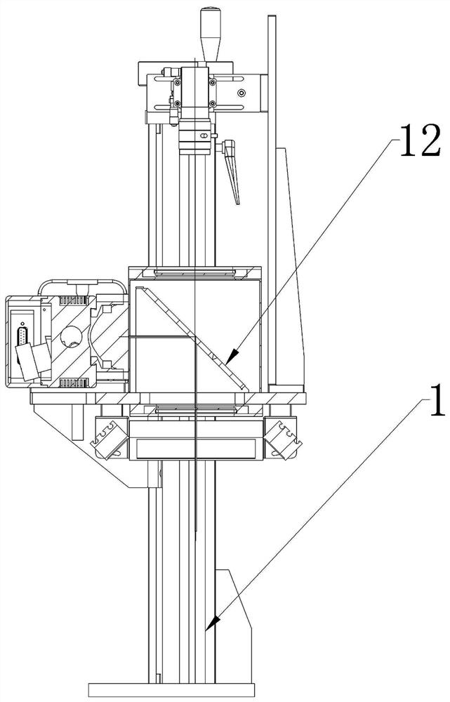
The utility model uses a pseudo-coaxial method, that is, by setting a reflector to couple the imaging of the laser and the visual camera. After the visual camera takes pictures, the image information is converted into coordinate information and sent to the laser marking head for marking. Although it has Small field of view and high positioning and marking accuracy; however, existing laser processing equipment still needs to customize different jigs for positioning according to different products during product processing, which increases processing costs and production cycle problems

Method used


Image

  • Laser processing device adopting pseudo-coaxial visual system
  • Laser processing device adopting pseudo-coaxial visual system
  • Laser processing device adopting pseudo-coaxial visual system

Examples


Embodiment Construction

[0027] In the description of the present invention, it should be noted that for orientation words, such as the terms "center", "horizontal", "longitudinal", "length", "width", "thickness", "upper", "lower" , "Front", "Back", "Left", "Right", "Vertical", "Horizontal", "Top", "Bottom", "Inner", "Outer", "Clockwise", "Counterclockwise " and other indication orientations and positional relationships are based on the orientations or positional relationships shown in the drawings, and are only for the convenience of describing the present invention and simplifying the description, rather than indicating or implying that the device or element referred to must have a specific orientation, or in a specific orientation. The structure and operation should not be construed as limiting the specific protection scope of the present invention.

[0028] In addition, terms such as "first" and "second" are used for descriptive purposes only, and cannot be understood as indicating or implying rel...


PUM


Abstract

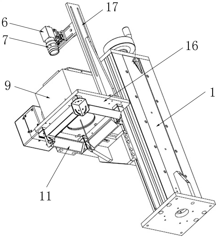
The invention discloses a laser processing device adopting a pseudo-coaxial visual system. The laser processing device comprises a galvanometer square head, an optical main beam, a focusing field lens, a camera, a lens, an upper sealing lens assembly, a sealing cover, a lower sealing lens assembly, an annular light source and a 45-degree reflecting lens. In actual work, working coordinates are adjusted and a laser processing path is controlled through the specific pseudo-coaxial visual system, targets in any shapes can be tracked, automatic identification, automatic detection positioning and automatic processing can be realized, so that a to-be-processed product does not need to be clamped and positioned by a tool clamp, the product can be processed as long as the product is flatly placed at any angle, midway material carrying and clamping of the to-be-processed product are reduced, the production efficiency is greatly improved, and the production process is simplified; and the problems of difficult feeding, poor positioning and low speed caused by difficult design and manufacturing of a clamp in batch irregular product marking are solved.

Description

technical field [0001] The invention relates to the technical field of laser processing devices, in particular to a laser processing device equipped with a visual camera for positioning. Background technique [0002] Laser processing is a technology for marking and cutting products. It uses focused high-power and high-density laser beams to irradiate the processed materials, so that the materials are quickly heated to the gasification temperature, and the deep substances are exposed by evaporation, or through The light energy burns away part of the material, showing various patterns such as patterns, characters, and barcodes that need to be etched. [0003] At present, in laser processing applications, the form of visual marking / engraving is very extensive. In visual laser processing equipment, the laser head and visual camera are usually set side by side, which has a large visual range and low product processing accuracy and processing efficiency. question. A Chinese util...

Claims


Application Information

Patent Timeline
IPC IPC(8): B23K26/00B23K26/70
CPCB23K26/00B23K26/702
Inventor 温国斌潘晓涛
Owner 广东国玉科技股份有限公司
Learn More