In-ceiling mount type air conditioner and indoor unit thereof

An air-conditioning device and ceiling technology, which is applied in the field of indoor units, can solve the problems of complex structure of components, increase of permanent magnet and plate manufacturing cost, etc., and achieve the effect of preventing noise and reducing sound

Active Publication Date: 2009-03-18
SANYO ELECTRIC CO LTD
View PDF3 Cites 10 Cited by
  • Summary
  • Abstract
  • Description
  • Claims
  • Application Information

AI Technical Summary

Problems solved by technology

[0011] However, in the air conditioner, the manufacturing cost necessary to manufacture the permanent magnet and the plate is increased, and at the same time, the corner panel and the d

Method used


Image

  • In-ceiling mount type air conditioner and indoor unit thereof
  • In-ceiling mount type air conditioner and indoor unit thereof
  • In-ceiling mount type air conditioner and indoor unit thereof

Examples


no. 1 approach

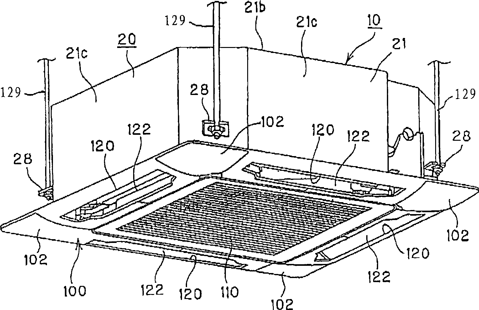
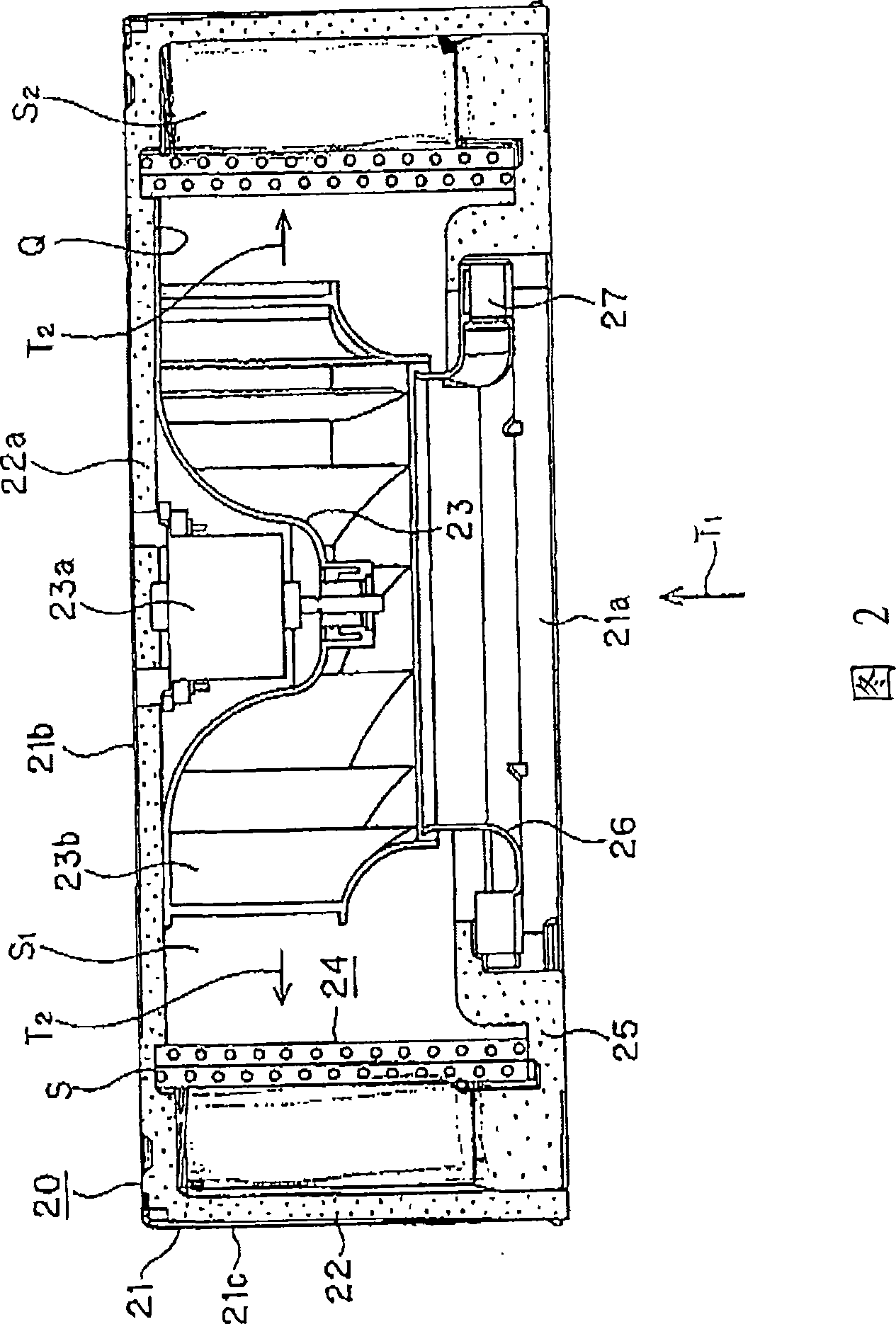
[0074] figure 1 It is a perspective view of the indoor unit 10 of the ceiling-embedded air conditioner viewed from the lower side, and FIG. 2 is a longitudinal sectional view of the indoor unit body 20 . In addition, in this embodiment, as an example of the indoor unit 10, although a four-way box-type small box-type indoor unit with an outer shape of 600mm×600mm is described, it is not limited thereto, and a two-way indoor unit may have a general outer shape. The four-way indoor unit is also applicable.

[0075] The indoor unit 10 of the air conditioner, such as figure 1 As shown, the indoor unit main body 20 is inserted into the installation opening provided on the ceiling from the indoor side; and the decorative panel 100 is installed on the indoor unit main body 20 from the lower side.

[0076] The indoor unit main body 20 has a casing 21 constituting its outer shape. The casing 21 is formed in a box shape, and is composed of a lower opening 21a that is open to the entir...

no. 2 approach

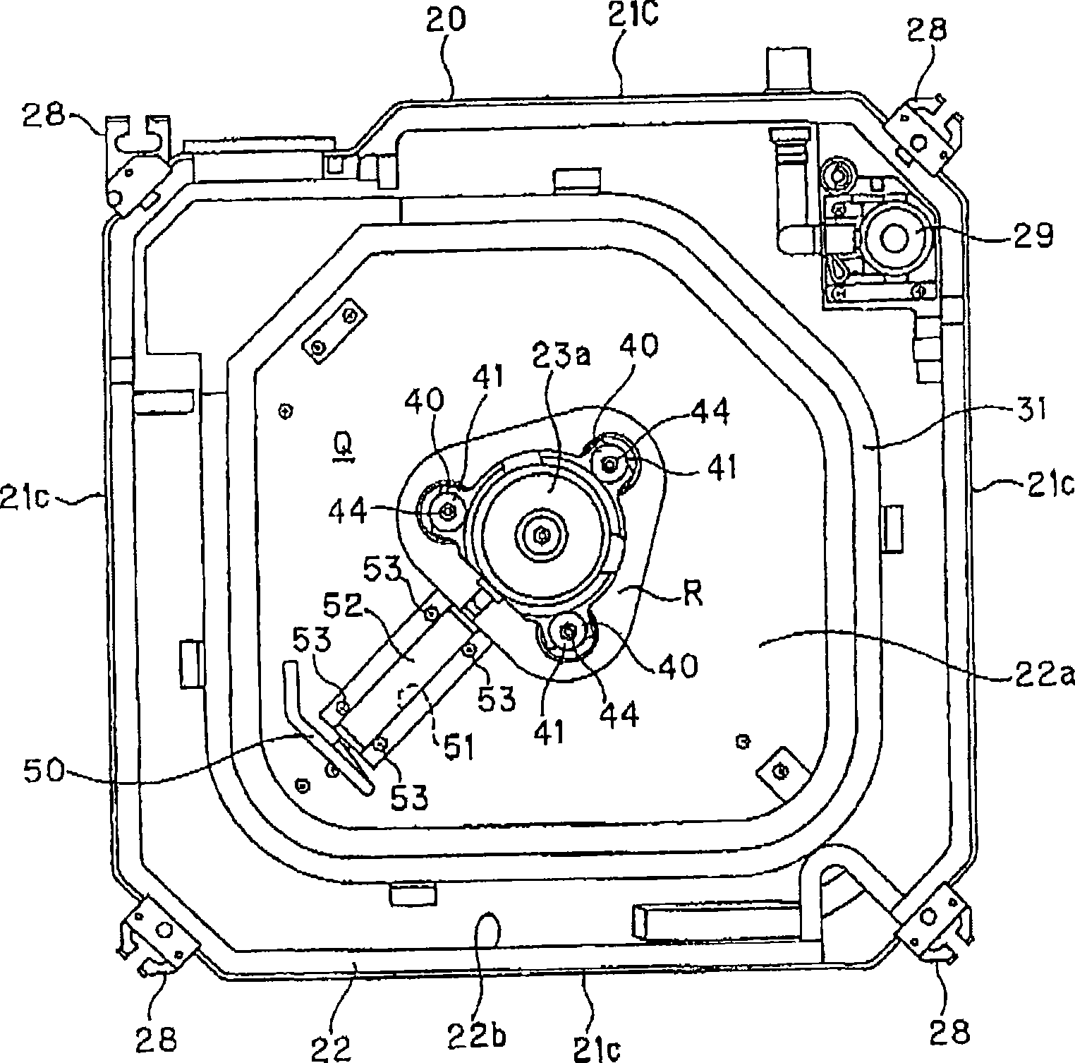
[0101] Figure 9 It is a perspective view enlargedly showing the air outlet 120 and the vane 122 formed in the decorative panel 100, and FIG. 10 is an enlarged view of the vane support portion. in addition, Figure 11 It is the state which removed the corner panel 130, and is a plan view which shows the state which mounted the mounting base of a stepping motor to the decoration panel 100. FIG. In addition, FIG. 12 is a perspective view showing the mounting base 30 of the stepping motor. FIG. 13 is a perspective view showing the flap 122 as a single body.

[0102] Inside the opening of the outlet 120, such as figure 1 and Figure 9 As shown, the fins 122 extend substantially along the entire length of the outlet 120 in the longitudinal direction. In addition, among the four corners of the decorative panel 100, Figure 11 One upper left corner shown on the paper is provided with two mounting bases 30 for supporting one end of the fin 122 in the longitudinal direction (ther...

no. 3 approach

[0125] FIG. 14 is a perspective view showing the housing 21 in which the suspension metal fittings 28 are assembled. Figure 15 It is a schematic diagram showing the procedure of assembling the suspension metal fittings 28 to the casing 21 .

[0126] As mentioned above, the four corners of the housing 21 are respectively fixed with suspension metal fittings 28 , and the suspension bolts 29 pass through the suspension metal fittings 28 , and the housing 21 is suspended from the ceiling by the suspension bolts 29 . The suspension metal parts 28 such as Figure 15 As shown, there are: a first part 31 , a second part 32 and a third part 33 . The first part 31 extends to the inner side of the casing 21; the second part 32 is equipped with a groove 32a (Fig. 14) through which the suspension bolt 29 passes, and when the opening (not shown) formed on the casing 21 is inserted along the arrow P When the first part 31 is rotated along the direction of the arrow R so that the facing su...


PUM


Abstract

An indoor unit of an in-ceiling mount type air conditioner includes a box-shaped housing having a top plate portion, a side plate portion and an opening portion at the lower portion thereof, a face panel detachably mounted on the opening portion of the housing, an indoor heat exchanger through which the inside of the housing is compartmented into a primary side and a secondary side, and an air blower secured to the top plate portion of the housing that faces the primary side, has a primary side heat insulating material is provided to the top plate portion so as to face the primary side of the housing and a secondary side heat insulating material provided to the side plate portion so as to face the secondary side of the housing, wherein the primary side heat insulating material is provided with an opening portion through which the air blower is fixed to the top plate portion.

Description

technical field [0001] The present invention relates to an indoor unit of a ceiling-embedded air conditioner in which the inside of a housing is insulated. Background technique [0002] Conventionally, the indoor unit of the ceiling-embedded air conditioner has a box-shaped housing with an opening on the lower side, and the inside of the housing is divided into a primary side space and a secondary side space by an indoor heat exchanger. The primary side space is divided by the top plate of the housing and the indoor heat exchanger, and the air before air conditioning is drawn from the room into the primary side space. In addition, the secondary side space is partitioned by the side plate portion, the top plate portion of the housing, and the indoor heat exchanger, and air-conditioned air is sent from the primary side space to the secondary side space. On the side plate portion and the top plate portion of the secondary side space facing the casing, a secondary side heat ins...

Claims


Application Information

Patent Timeline
IPC IPC(8): F24F1/00F16L59/05F24F13/20
CPCF24F2001/0037F24F1/0047
Inventor 古贺诚一小仓信博林贵一
Owner SANYO ELECTRIC CO LTD
Why Eureka
Try Eureka