Double source double energy straight-line type safety inspection CT apparatus and inspection method thereof

A dual-energy, straight-line technology, used in measuring devices, instruments, scientific instruments, etc., can solve problems such as inability to effectively distinguish

Inactive Publication Date: 2009-03-18
CHONGQING UNIV
0 Cites 13 Cited by

AI-Extracted Technical Summary

Problems solved by technology

However, the scanning path of this device is a linear scan with a finite length, which is equivalent to a CT scan with a limited angle. The reconstruction of the object to be detected is an approximate reconstruction, and the qualit...

Abstract

The invention discloses a two-source two-energy linear security inspection CT device and a detection method thereof, wherein a ray generator and a data collector are connected with a control and image processing system, the ray generator comprises a high energy ray generator and a low energy ray generator, a high energy data collector and a low energy data collector are arranged correspondingly with the high energy ray generator and the low energy ray generator, the high energy ray generator and the low energy ray generator are horizontally arranged at the side surface of an object transmitter, which rays are cornered of 90 degrees. The invention can effectively recognize the matters of similar densities and different atom numbers, can quickly and accurately recognize suspected matters as well as obtain the sectional image and the three-dimension image of the suspected region of the object. The two-source two-energy linear security inspection CT device has simple structure and low production cost. The invention adopts reconstruction and fusion methods to analyze data and can effectively recognize the dangerous materials of objects.

Application Domain

Material analysis by transmitting radiation

Technology Topic

Amount of substanceData collector +8

Image

  • Double source double energy straight-line type safety inspection CT apparatus and inspection method thereof
  • Double source double energy straight-line type safety inspection CT apparatus and inspection method thereof
  • Double source double energy straight-line type safety inspection CT apparatus and inspection method thereof

Examples

  • Experimental program(1)

Example Embodiment

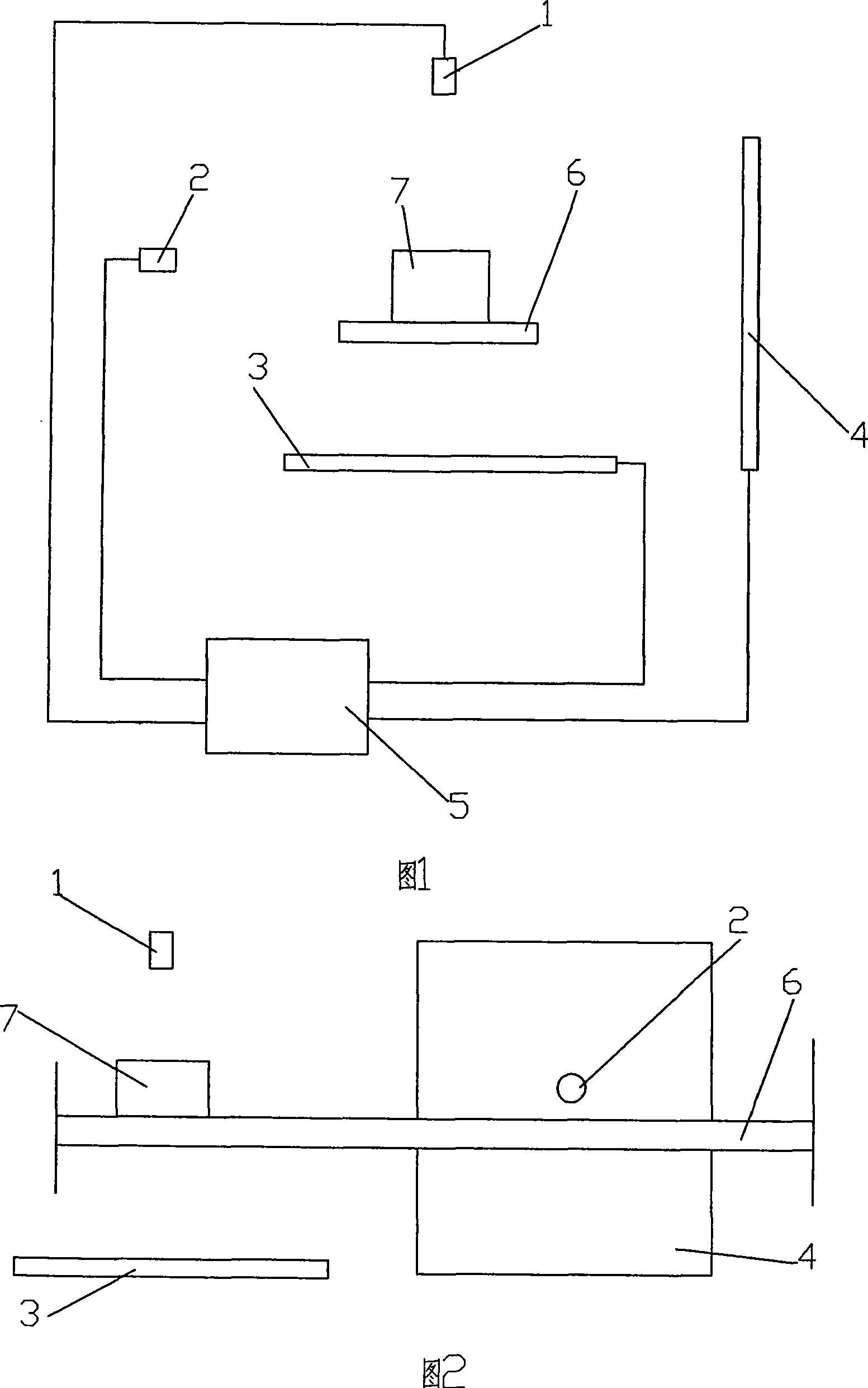
[0055] Figure 1 is a schematic structural diagram of the present invention, and Figure 2 is a schematic structural layout of the present invention, as shown in the figure: the dual-source dual-energy linear security inspection CT device of the present invention includes a radiation generating device, a data acquisition device, a control and an image processing system 5 It is connected with the object conveying device 6, the ray generating device and the data acquisition device with the control and image processing system. The ray generating device includes a high-energy ray generating device 1 and a low-energy ray generating device 2, and a high-energy data acquisition device is set corresponding to the high-energy ray generating device 1. The device 3 is provided with a low-energy data acquisition device 4 corresponding to the low-energy ray generating device 2, and the beams of the high-energy ray generating device and the ray beams of the low-energy ray generating device are arranged at an angle of 90° to each other in the transverse direction; the high-energy data acquisition device 3 and the low-energy data acquisition device 4 are respectively area array detectors containing a plurality of detector units; in this embodiment, the high-energy ray generating device 1 and the low-energy ray generating device 2 are in different transverse sections, which can partially or completely eliminate the high-energy ray generating device 1 Interference with the ray beams of the low-energy ray generating device 2 helps to more accurately judge whether there are dangerous goods in the object to be detected; of course, it can also be scanned at the same cross section at the same time, and the purpose of the invention can also be achieved; this implementation In the example, the object conveying device 6 moves horizontally, and the high-energy ray generating device 1 and the low-energy ray generating device 2 are respectively arranged on the side and the upper side of the object conveying device.
[0056] image 3 It is a block diagram of the detection method of the present invention, Figure 4 It is a schematic diagram of the coordinate system of the present invention, as shown in the figure: Figure 4 Among them, the moving direction of the object 7 to be inspected is the x-axis, the horizontal direction is the y-axis, and the height direction is the z-axis; the method for safety detection by a dual-source dual-energy linear security inspection CT device includes the following steps:
[0057] a. Start the ray generating device, data acquisition device, control and image processing system and the conveying device of the inspected object;
[0058] b. The ray beams of the high-energy ray generator and the low-energy ray generator penetrate the object 7 on the object delivery device, and the high-energy data acquisition device and the low-energy data acquisition device collect data and send it to the control and image processing system for transmission projection Data noise reduction and consistency correction preprocessing, solving the effective atomic number and determining the geometric parameters of the object to be inspected, analyzing the perspective image, judging whether there is a suspicious area, if not, then ending the inspection, if it exists, using finite line integration The method of (Finit Line IntegralTransform) tracks the suspected area in the object to be detected 7;
[0059] c. If there is a suspect area in the image judged in step b, a tomographic image and a three-dimensional image of the suspect area in the object to be detected are reconstructed from two sets of transmission projection data of the high-energy data acquisition device and the low-energy data acquisition device;
[0060] As a new method based on multi-scale geometric analysis in recent years, finite line integral transformation uses a series of fixed templates or modules of different scales to analyze image or volume data, especially suitable for the analysis of line features in image or volume data.
[0061] When the high-energy data acquisition device and the low-energy data acquisition device collect data simultaneously, the ray beam S of the low-energy ray generating device 1 The projection of P is denoted as p 11 (l, u 1 , v 1 ), the reconstruction formula of the object to be detected is as follows,
[0062] g 11 ( r 11 , φ 11 , z ) = ∫ - θ 1 , m θ 1 , m dθ 1 ∫ - t 1 , m t 1 , m p 11 % ( t ′ , θ 1 , v ) h ( t - t ′ ) dt ′
[0063] in,
[0064] p 11 % ( t ′ , θ 1 , v ) = p 11 ′ ( R S 1 x ( R S 1 + y ) 2 + x 2 , tan - 1 ( x R S 1 + y ) , v )
[0065] p 11 ′ ( l , u , v ) = R S 1 2 + u 2 R S 1 2 + u 2 + v 2 p 11 ( l , u , v )
[0066] u = R S 1 x R S 1 + y , v = R S 1 z R S 1 + y
[0067] x=l+r 11 cosφ 11 , y=r 11 sinφ 11
[0068] High-energy ray generator beam S 2 The projection of P is denoted as p 12 (l, u 2 , v 2 ), the reconstruction formula of the object to be detected is as follows,
[0069] g 12 ( r 12 , φ 12 , y ) = ∫ - θ 2 , m θ 2 , m dθ 2 ∫ - t 2 , m t 2 , m p 12 % ( t ′ , θ 2 , v ) h ( t - t ′ ) dt ′
[0070] in,
[0071] p 12 % ( t ′ , θ 2 , v ) = p 12 ′ ( R S 2 x ( R S 2 - z ) 2 + x 2 , tan - 1 ( x R S 2 - z ) , v )
[0072] p 12 ′ ( l , u , v ) = R S 2 2 + u 2 R S 2 2 + u 2 + v 2 p 12 ( l , u , v )
[0073] u = R S 2 x R S 2 - z , v = R S 1 y R S 1 - z
[0074] x=l+r 12 cosφ 12 , z=r 12 sinφ 12
[0075] When the data collected by the high-energy data acquisition device and the low-energy data acquisition device are not carried out simultaneously, the ray beam S of the low-energy ray generating device 1 The projection of P' is denoted as P 21 (l, u 1 , v 1 ), the virtual detector center of the low-energy center in the control and image processing system The coordinates are (x 01 , 0, z), the reconstruction formula of the object to be detected is as follows,
[0076] g 21 ( r 21 , φ 21 , z ) = ∫ - θ 1 , m θ 1 , m d θ 1 ′ ∫ - t 1 , m t 1 , m p 21 % ( t ′ , θ 1 ′ , v ) h ( t - t ′ ) dt ′
[0077] in,
[0078] p 21 % ( t ′ , θ 1 ′ , v ) = p 12 ′ ( R S 1 ′ x - x 01 ( R S 1 ′ + y ) 2 + ( x - x 01 ) 2 , tan - 1 ( x - x 01 R S 1 ′ + y ) , v )
[0079] p 21 ′ ( l , u , v ) = R S 1 ′ 2 + u 2 R S 1 ′ 2 + u 2 + v 2 p 21 ( l , u , v )
[0080] u = R S 1 ′ ( x - x 01 ) R S 1 ′ + y , v = R S 1 ′ z R S 1 ′ + y
[0081] x=l+r 21 cosφ 21 , y=r 21 sinφ 21
[0082] High-energy ray generator beam S 2 The projection of P' is denoted as p 22 (l, u 2 , v 2 ), virtual detector center of high energy center in control and image processing system The coordinates are (x 02 , y, 0), the reconstruction formula of the object to be detected is as follows,
[0083] g 22 ( r 22 , φ 22 , z ) = ∫ - θ 2 , m θ 2 , m d θ 2 ′ ∫ - t 2 , m t 2 , m p 22 % ( t ′ , θ 2 ′ , v ) h ( t - t ′ ) dt ′
[0084] in,
[0085] p 22 % ( t ′ , θ 2 ′ , v ) = p 22 ′ ( R S 2 ′ x - x 02 ( R S 2 ′ - z ) 2 + ( x - x 02 ) 2 , tan - 1 ( x - x 02 R S 2 ′ - z ) , v )
[0086] p 22 ′ ( l , u , v ) = R S 2 ′ 2 + u 2 R S 2 ′ 2 + u 2 + v 2 p 22 ( l , u , v )
[0087] u = R S 2 ′ ( x - x 02 ) R S 2 ′ - z , v = R S 2 ′ y R S 2 ′ - z
[0088] x=l+r 22 cosφ 22 , z=r 22 sinφ 22
[0089] In the formula: P, P'represent the reconstructed object point to be detected, S 1stands for low-energy ray source, S 2 represents a high-energy ray source, O 1 represents the center of the low-energy area detector, O 2 Represents the center of the high energy area array detector, O is S 1 o 1 and S 2 o 2 The intersection of connecting lines, O' is S 1 o 1 and S 2 o 2 midpoint of the vertical line, S 1 The distance to O is denoted as R S1 , S 1 The distance to O' is recorded as R S1' , S 2 The distance to O is denoted as R S2 , S 2 The distance to O' is recorded as R S2' , the center coordinates of the object to be detected are (l, 0, 0), and the coordinate systems of the high-energy and low-energy detectors are respectively u 1 -v 1 and u 2 -v 2 , u 1 , u 2 Parallel to the x-axis, v 1 Parallel to the z-axis, v 2 Parallel to the y-axis, θ 1,m =tan -1 (u 1,m /RS 1 ), u 1,m is the half-width of the low-energy detector in the x direction, t 1,m is the maximum value of the coordinates of the low-energy detector in the x direction after the rearrangement of the low-energy ray beam, θ 2,m =tan -1 (u 2,m /R S2 ), u 2,m is the half-width of the high-energy detector in the x direction, t 2,m is the maximum value of the high-energy detector in the x-direction after rearrangement of the high-energy ray beam, h(t) is the slope filter, S 1 P has length r 11 , S 2 P has length r 12 , S 1 The length of P' is r 21 , S 2 The length of P' is r 22 , S 1 The angle between P and the x direction is φ 11 , S 2 The angle between P and the x direction is φ 12 , S 1 The angle between P' and the x direction is φ 21 , S 2 The angle between P' and the x direction is φ 22 , g 11 (r 11 , φ 11 , z), g 21 (r 21 , φ 21 , z) is S 1 The reconstruction coordinates of the object to be detected established by taking the center coordinates of the object to be detected as the origin of the polar coordinates on the central plane, g 12 (r 12 , φ 12 , y), g 22 (r 22 , φ 22 , y) is S 2 The reconstruction coordinates of the object to be detected are established on the center plane where the center coordinate of the object to be detected is taken as the origin of the polar coordinates.
[0090] Use the reconstructed image to further judge the nature of the suspected area, decide whether to exclude the suspect or keep the suspect, and determine whether there is any dangerous goods in it. If not, the inspection process will end; Judging the nature of the suspected area and determining the type of dangerous goods; if the type is determined successfully, the inspection process will end; if the type is not determined successfully, the object to be detected can be handed over to the security personnel for manual inspection and confirmation.
[0091] The fusion between high and low energy reconstructed images mainly adopts feature-level fusion and decision-level fusion. Feature-level fusion needs to extract features (such as edges, contours, shapes, and mutual distances of dangerous goods) from high- and low-energy reconstructed images and integrate them to obtain judgment results with higher confidence, which is suitable for the determination of knives and guns. Decision-making level fusion first determines the types of dangerous substances for high and low energy images, and then directly makes the optimal decision according to certain criteria and the credibility of each decision, which is suitable for the determination of organic substances (such as explosives and drugs). Specific methods such as Bayesian method, evidence reasoning method, neural network method, fuzzy set theory method, rough set theory method.
[0092] It also includes compression storage of projection data, tomographic images and three-dimensional images, lossless compression storage for suspect areas, low loss compression storage for non-suspect areas but containing objects to be detected, and non-suspect areas without objects to be detected The implementation of compressed storage with high loss rate.
[0093] Finally, it is noted that the above embodiments are only used to illustrate the technical solutions of the present invention without limitation. Although the present invention has been described in detail with reference to the preferred embodiments, those of ordinary skill in the art should understand that the technical solutions of the present invention can be carried out Modifications or equivalent replacements without departing from the spirit and scope of the technical solution of the present invention shall be covered by the claims of the present invention.

PUM

no PUM

Description & Claims & Application Information

We can also present the details of the Description, Claims and Application information to help users get a comprehensive understanding of the technical details of the patent, such as background art, summary of invention, brief description of drawings, description of embodiments, and other original content. On the other hand, users can also determine the specific scope of protection of the technology through the list of claims; as well as understand the changes in the life cycle of the technology with the presentation of the patent timeline. Login to view more.
Why Eureka
Try Eureka