Wireless remote control system

A wireless remote control, wireless transceiver module technology, applied in signal transmission systems, instruments, data exchange through path configuration, etc., can solve the problems of signal interference, non-compliance, and a small number of address codes, and achieve the effect of reliable remote control

Inactive Publication Date: 2009-03-18
JIANGSU HUITONG GRP
View PDF0 Cites 12 Cited by
  • Summary
  • Abstract
  • Description
  • Claims
  • Application Information

AI Technical Summary

Problems solved by technology

[0003] Fixed-code and rolling-code remote control devices have their own characteristics. Fixed-code chips are cheap, but the number of address codes is small. For example, the most used PT2262 on the market has only 6561, and the probability of repeated codes is high.
Rolling coding chip has low probability of recoding and good anti-cracking performance, but the price is more expensive, and it must be "code-checked" before it can be put into work, which is relatively troublesome
[0004] The above-mentioned remote control system also has the following disadvantages: 1. The data of the receiving end and the sending end are pre-written in the program, which is not easy to change, and does not meet any standards
2. It is easy to send signal interference, because the signal sent by the sending end is not bound to the identity of the sending end, and the data code sent is open. In the case of repeated codes, multiple sending ends can control the same receiving end
3. One-to-many control cannot be realized, because the sending end and the receiving end have been paired before leaving the factory, so one sending end cannot control multiple receiving ends of different types
4. Networking between multiple remote control devices is not possible, because the data transmission does not conform to any protocol, so the protocol networking between devices cannot be carried out

Method used


Image

  • Wireless remote control system
  • Wireless remote control system
  • Wireless remote control system

Examples


Embodiment 1

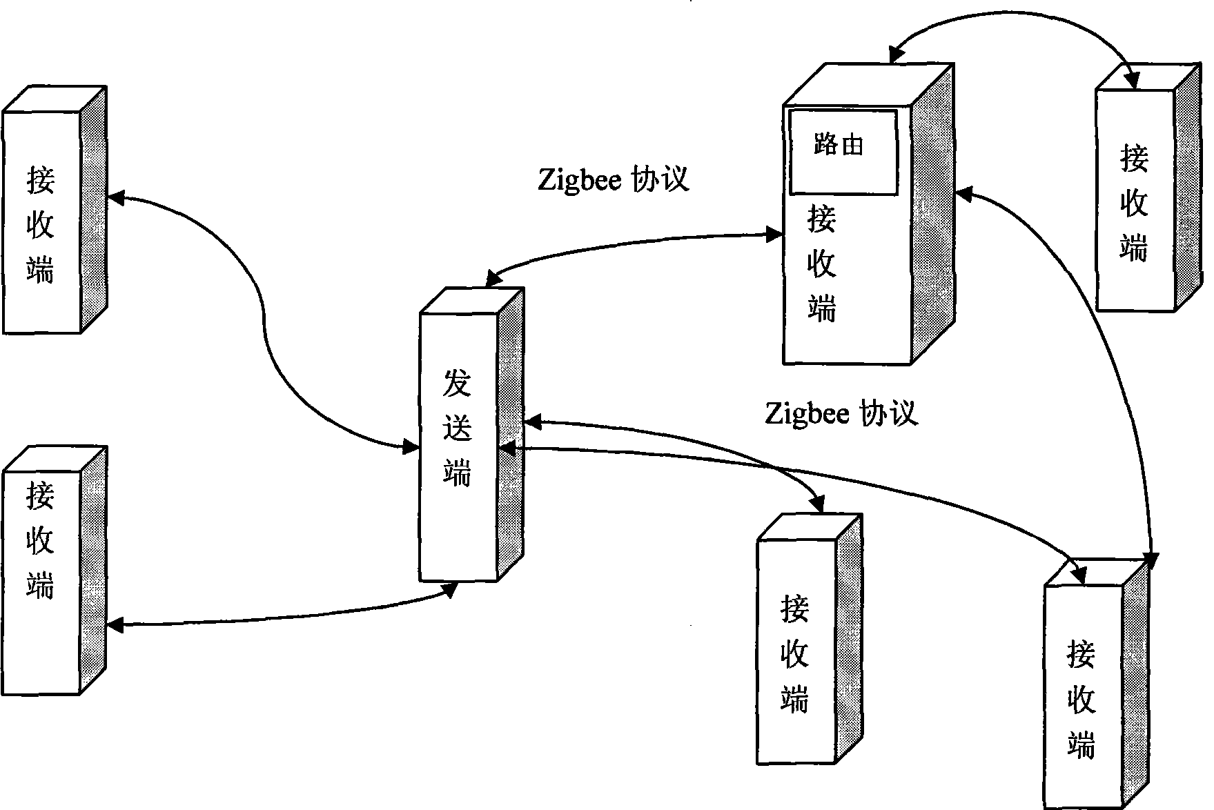
[0026] Such as figure 1 As shown, a remote control system includes a sending end and several receiving ends, the sending end and the receiving end are wirelessly connected, the bottom layer of the sending end and the receiving end is based on the Zigbee protocol, and the entire structure and protocol are compatible with Zigbee on the market The product is compatible. The data of the sending end and the receiving end are bidirectionally transmitted. The sending end can not only control the receiving end, but the information of the receiving end can also be read back by the sending end. The data is encrypted (AES) and verified to ensure the correctness of the data. Some receivers are equipped with wireless routers, which act as network nodes for signal forwarding, that is, to transmit the signals of the transmitter to other receivers and to transmit the signals of other receivers to the transmitter.

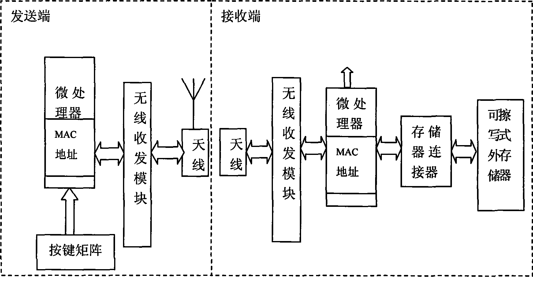
[0027] Such as figure 2 As shown, the sending end is provided with a first ...

Embodiment 2

[0030]The transmitting end and the receiving end in the present embodiment are as shown in Figure 3, and the first microprocessor chip, keyboard, removable erasable memory (EPROM), memory interface, wireless transceiver module and antenna are arranged in the transmitting end, and the keyboard passes through The matrix is ​​connected with the I / O port of the chip, and the wireless transceiver module is connected with the first microprocessor chip by accessing through the normal I / O port. A MAC address corresponding to the sending end is set in the memory of the first microprocessor chip. The address of the receiving end bound to it is stored in the removable erasable memory (EPROM). The USB port is converted from UART. A USB-to-serial chip is used to send the serial signal to the computer or other receiving end through the USB cable. The computer or other receiving end can also wirelessly control the receiving end controlled by the sending end.

[0031] The receiving end is pr...

Embodiment 3

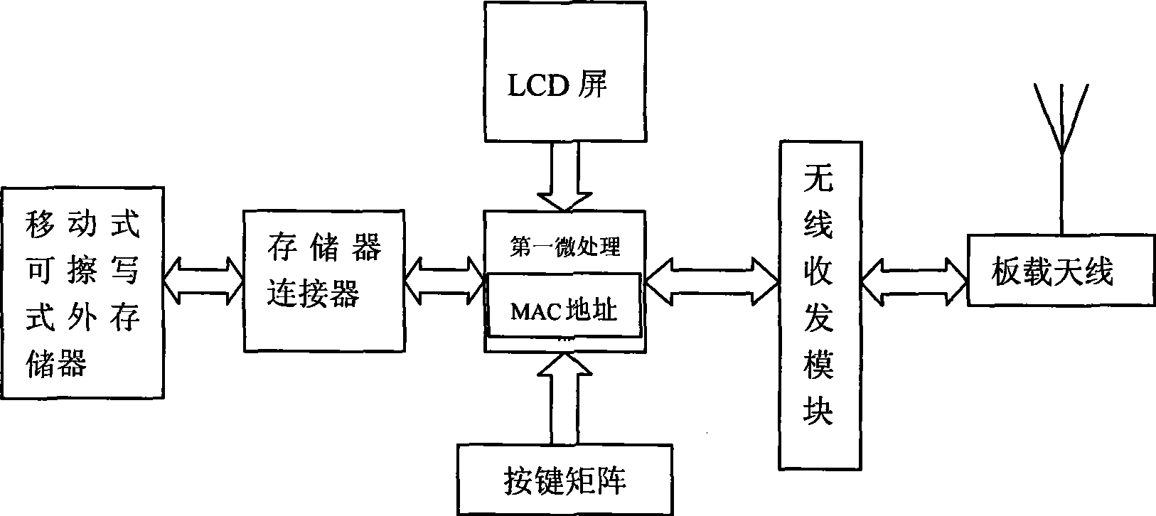
[0034] Such as Figure 4 , the sending end is composed of the first microprocessor chip, keyboard, mobile erasable memory, memory interface, USB port, LCD screen, wireless transceiver module and antenna, the mobile erasable memory communicates with the first microprocessor chip through the memory interface connection, the keyboard is connected to the I / O port of the chip through a matrix, accessed through the normal I / O port, the wireless transceiver module is connected to the first microprocessor chip, the antenna is connected to the wireless transceiver module, and the first microprocessor chip A MAC address corresponding to the sending end is set in the memory of the processor chip. The LCD screen is used to display status information, and the LCD screen communicates with the microprocessor chip through the SPI line. The USB port is converted from UART. A USB-to-serial chip is used to send the serial signal to the computer or other receiving end through the USB cable. The ...


PUM


Abstract

The invention relates to a wireless remote control system, which aims at providing a wireless remote control system which has strong anti-interference ability, can achieve one-to-multiple control and multiple-to-one control, and forms a wireless remote control equipment network. The technical proposal is that the wireless remote control system comprises at least one transmitting end and a receiving end, wherein the transmitting end and the receiving end are connected. A first microprocessor chip, a keyboard, a wireless receiving-transmitting module and an antenna are arranged in the transmitting end, wherein the keyboard is connected with an I/O hole of the chip through a matrix mode, the wireless receiving-transmitting module is connected with the first microprocessor chip, the antenna and the wireless receiving-transmitting module are connected, and a MAC address which is corresponding to the transmitting end is arranged in a memory of the first microprocessor chip. A second microprocessor chip, a wireless receiving-transmitting module, an antenna and an actuating mechanism are arranged in the receiving end, wherein the actuating mechanism and the wireless receiving-transmitting module are respectively connected with the second microprocessor chip, and a MAC address which is corresponding to the receiving end is arranged in a memory of the second microprocessor chip.

Description

technical field [0001] The invention relates to the field of wireless remote control, in particular to a wireless remote control system. technical background [0002] Use the wireless method to complete the remote control operation. The common ones are wireless remote control switch light, wireless remote control various electric toys, wireless remote control door switch, switch lock, wireless remote control car anti-theft alarm and various industrial wireless remote control, etc. The wireless remote control is divided into two parts: sending and receiving. The sending part is the wireless remote control. Its principle is to encode the control command and send it out through modulation. After the receiving circuit receives the remote control signal, it obtains the control command through decoding, remote control coding and decoding. It is further divided into two types: fixed encoding and rolling encoding. Typical fixed encoding chips such as PT2262, V1526, RT6588, etc., typ...

Claims


Application Information

Patent Timeline
Patent Type & Authority Applications(China)
IPC IPC(8): G08C17/02H04L12/28
Inventor 刘正东龙江程明慧龙涛
Owner JIANGSU HUITONG GRP
Why Eureka
Try Eureka