Circuit system with supply voltage for driving an electromechanical switch

A technology of electrical systems and circuits, applied in the direction of protection switches, electrical switches, electrostatic relays/electro-adhesion relays using micro-machines, etc., can solve the problems of expensive, large volume, dense area, etc.

Inactive Publication Date: 2009-03-18
GENERAL ELECTRIC CO
View PDF0 Cites 8 Cited by
  • Summary
  • Abstract
  • Description
  • Claims
  • Application Information

AI Technical Summary

Problems solved by technology

With the trend towards miniaturization of components in power electronics, winding processes often result in heavy, bulky devices
For example, planar transformers formed on semiconductor substrates or PCBs are more compact, but are still complex, expensive, area-intensive, and limit the range of available operating power

Method used


Image

  • Circuit system with supply voltage for driving an electromechanical switch
  • Circuit system with supply voltage for driving an electromechanical switch
  • Circuit system with supply voltage for driving an electromechanical switch

Examples


Embodiment Construction

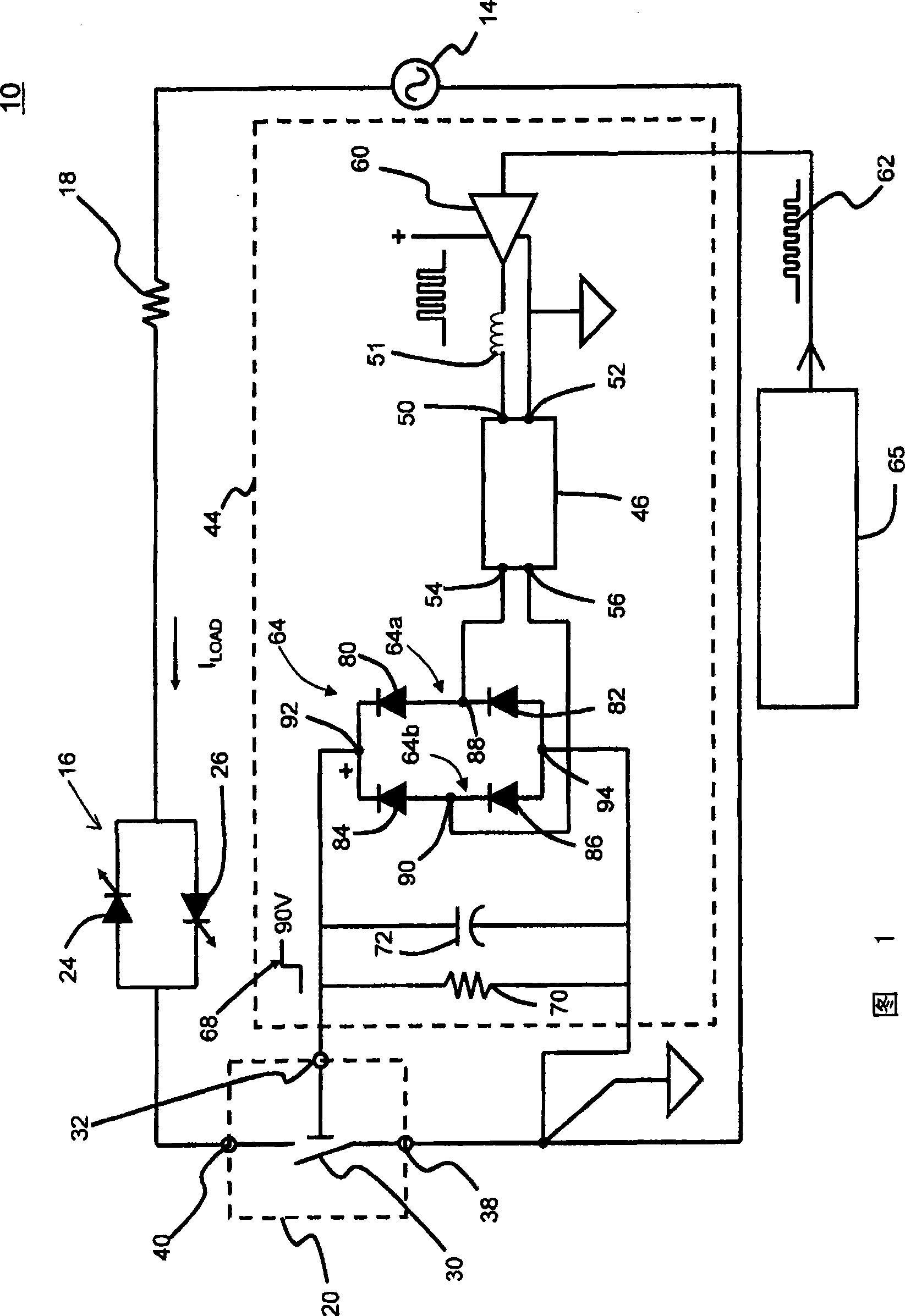
[0015] Currently, micro-electromechanical systems (MEMS) generally refer to micron-scale structures, which can integrate multiple different elements, such as mechanical elements, electromechanical elements, sensors, actuators, and electronic devices, on a common substrate, for example, by microfabrication techniques. Switching technologies for MEMS applications include semiconductor devices, such as power field effect transistors (FETs) and insulated gate bipolar transistors (IGBTs), and include MEMS switches that are electromechanical in nature. An example of a MEMS switch includes a gate that controls an electrostatically actuated beam. The beam can be shifted between two positions to make the switch conductive or non-conductive.

[0016] Such MEMS switches have substantially different requirements than semiconductor switches, which typically require a gate drive for low voltage startup, eg less than 18V. On the other hand, current MEMS switches require relatively high volt...


PUM


Abstract

The invention discloses a circuit system with supply voltage for driving an electromechanical switch. A circuit (10) for controlling operation of a load (16) is disclosed. In one example, a MEMS switch (20) is positioned in the circuit(10) to place the load (16) in one of a conducting state or a nonconducting state. A piezoelectric transformer (46) provides a relatively high voltage output signal or a relatively low voltage output signal to control movement of the switch (20) between a closed position, placing the load in the conducting state, and an open position. The high voltage output signal includes a frequency component in the resonant frequency range of the transformer (46). Control circuitry (65) provides an input voltage signal to the piezoelectric transformer (46) to provide the high voltage output signal or the low voltage output signal at the output terminals of the piezoelectric transformer (46).

Description

technical field [0001] The present invention relates generally to voltage conversion, and more particularly to circuits and systems incorporating current loads and switches for controlling current flowing therethrough. Background technique [0002] Electromechanical switches are typically gated into a conducting or non-conducting state using a switching DC voltage power supply or a switching AC power supply. Many applications require very fast switching characteristics, which can be achieved using microelectromechanical (MEMS) switches. This switch has unique voltage and current characteristics and can achieve switching speeds of about 3 to 20 microseconds. As the size of switching components continues to shrink, the characteristics of a driver circuit that can provide acceptable performance and package size are becoming more demanding. [0003] In many power circuit applications, including, for example, televisions and fluorescent lamps, wire wound electromagnetic transfo...

Claims


Application Information

Patent Timeline
Patent Type & Authority Applications(China)
IPC IPC(8): H01H47/00H01H9/54H01H59/00H02M5/32H02M7/06H02M1/14H05B37/02
CPCH01H2071/008H01H1/0036H01H59/0009B81B7/02H01H9/54
Inventor J·I·赖特K·苏布拉马尼安N·C·R·赫其斯J·N·帕克
Owner GENERAL ELECTRIC CO
Why Eureka
Try Eureka