Control method and control device for driving hydraulic system of engineering vehicle by single pump and double motors

A technology for hydraulic systems and engineering vehicles, which is applied in the direction of fluid pressure actuators, servo motors, servo motor components, etc., and can solve problems that affect the service life of hydraulic pumps, reduce the traction force of the whole machine, and reduce work efficiency, so as to improve operating efficiency , prolong the service life and prevent the effect of unilateral slipping

Active Publication Date: 2009-03-25
SANY GRP
View PDF0 Cites 12 Cited by
  • Summary
  • Abstract
  • Description
  • Claims
  • Application Information

AI Technical Summary

Problems solved by technology

[0004] Usually, all-hydraulic drive engineering vehicles mostly use a single-pump, dual-motor system, and the hydraulic oil output by the hydraulic pump is freely distributed to the oil circuit where the two hydraulic motors are located, so it has certain defects. When working on small roads, if anti-skid measures are not taken, unilateral slipping is more likely to occur; this not only seriously affects the service life of hydraulic components such as hydraulic pumps and hydraulic motors, but also reduces the traction force of the whole machine and reduces work efficiency

Method used


Image

  • Control method and control device for driving hydraulic system of engineering vehicle by single pump and double motors
  • Control method and control device for driving hydraulic system of engineering vehicle by single pump and double motors
  • Control method and control device for driving hydraulic system of engineering vehicle by single pump and double motors

Examples


Embodiment Construction
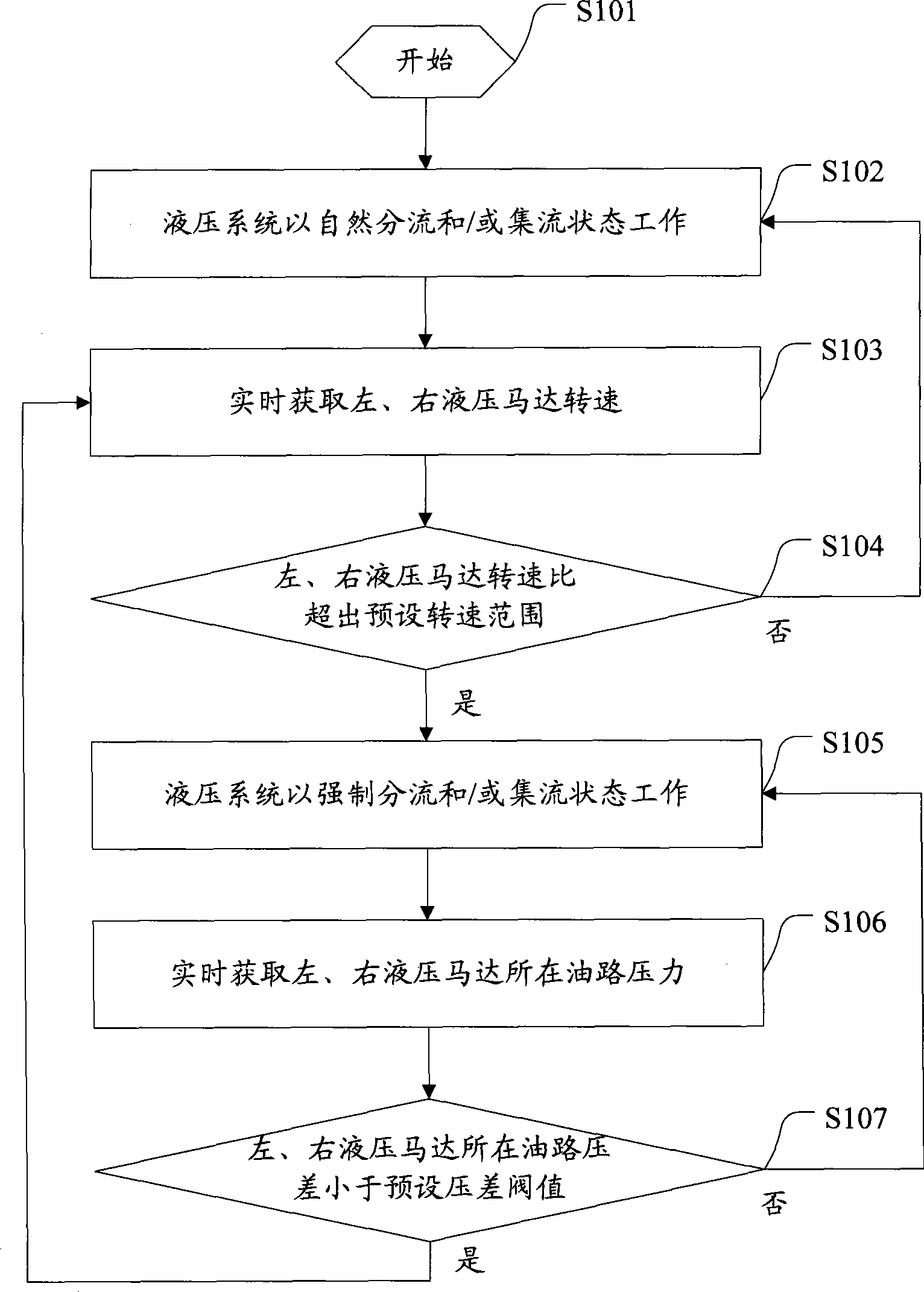
[0028] The basic idea of ​​the present invention is: control the hydraulic system according to the working conditions to switch between the natural diversion and / or flow concentrating state and the forced diversion and / or concentrating state; 1. When the speed ratio of the right hydraulic motor exceeds the preset speed ratio range, the hydraulic system is controlled to forcibly divide and / or flow; in the state of forced flow and / or flow, when the pressure difference between the two branches of the diverter valve is judged, Control the hydraulic system to return to the natural flow diversion and / or flow collection state.

[0029] Wherein: the state of natural diversion and / or concentration includes two states of natural diversion and natural concentration; the state of forced diversion and / or concentration includes two states of forced diversion and forced concentration. For the sake of convenience, in the present invention, the concepts of flow diversion and / or flow concentrat...


PUM


Abstract

The invention discloses a method for controlling an engineering vehicle hydraulic system which is driven by a single pump and two motors. The method comprises the following steps: in a state of natural split flow and / or flow combine, obtaining the rotating speeds of a left hydraulic motor and a right hydraulic motor in real time; judging whether the rotating speed ratio of the left hydraulic motor to the right hydraulic motor exceeds the range of a preset rotating speed ratio; if the rotating speed ratio exceeds the range of the preset rotating speed ratio, controlling the hydraulic system to be in a state of enforced split flow and / or flow combine; in the state of enforced split flow and / or flow combine, obtaining the pressure on an oil path of the left and the right hydraulic motors in real time; judging whether the pressure on the oil path of the left and the right hydraulic motors is smaller than a preset differential pressure threshold value; and if the pressure is smaller than the preset differential pressure threshold value, controlling the hydraulic system to return to the state of natural split flow and / or flow combine. Through controlling the state of the hydraulic system to be switched between the state of natural split flow and / or flow combine and the state of enforced split flow and / or flow combine, the method can avoid the problem of single-side skid of an engineering vehicle and improves the self adaptability and the working efficiency of the engineering vehicle. On the basis, the invention also discloses a control device for the engineering vehicle hydraulic system which is driven by the single pump and the two motors.

Description

technical field [0001] The invention relates to the technical field of hydraulic transmission and control, in particular to a control method and a control device for a hydraulic system of an engineering vehicle driven by a single pump and two motors. Background technique [0002] Hydraulic transmission uses liquid as the working medium to transmit energy. It has good control characteristics and has inherent advantages in low-speed high-torque transmission, frequent start-stop reversing, micro-speed action and inching operation. At present, with the development of hydraulic technology at home and abroad, the performance of hydraulic components has been continuously improved, and the price has been continuously reduced. Hydraulic transmission and control technology has been widely used in construction machinery. [0003] The power transmission route of the full hydraulic drive engineering vehicle is: engine→coupling→hydraulic pump→hydraulic motor→reduction balance box→wheels. ...

Claims


Application Information

Patent Timeline
Patent Type & Authority Applications(China)
IPC IPC(8): F15B13/06F15B13/044F15B11/16F15B11/04
Inventor 李建科郑鹏飞陈强
Owner SANY GRP
Why Eureka
Try Eureka