Ultra-wideband flat helical antenna having back chamber

A planar helical, ultra-wideband technology, applied in the directions of antennas, electrical components, radiating components, etc., can solve the problems of complex photonic band gap structure and limited effect, and achieve excellent performance, simple structure, and low profile.

Inactive Publication Date: 2009-03-25
SHANGHAI JIAO TONG UNIV
View PDF1 Cites 18 Cited by
  • Summary
  • Abstract
  • Description
  • Claims
  • Application Information

AI Technical Summary

Problems solved by technology

However, the photonic bandgap structure is relatively complex, and the effect is very limited.

Method used


Image

  • Ultra-wideband flat helical antenna having back chamber
  • Ultra-wideband flat helical antenna having back chamber
  • Ultra-wideband flat helical antenna having back chamber

Examples


Embodiment Construction

[0016] The embodiments of the present invention are described in detail below in conjunction with the accompanying drawings: this embodiment is implemented on the premise of the technical solution of the present invention, and detailed implementation methods and specific operating procedures are provided, but the protection scope of the present invention is not limited to the following the described embodiment.

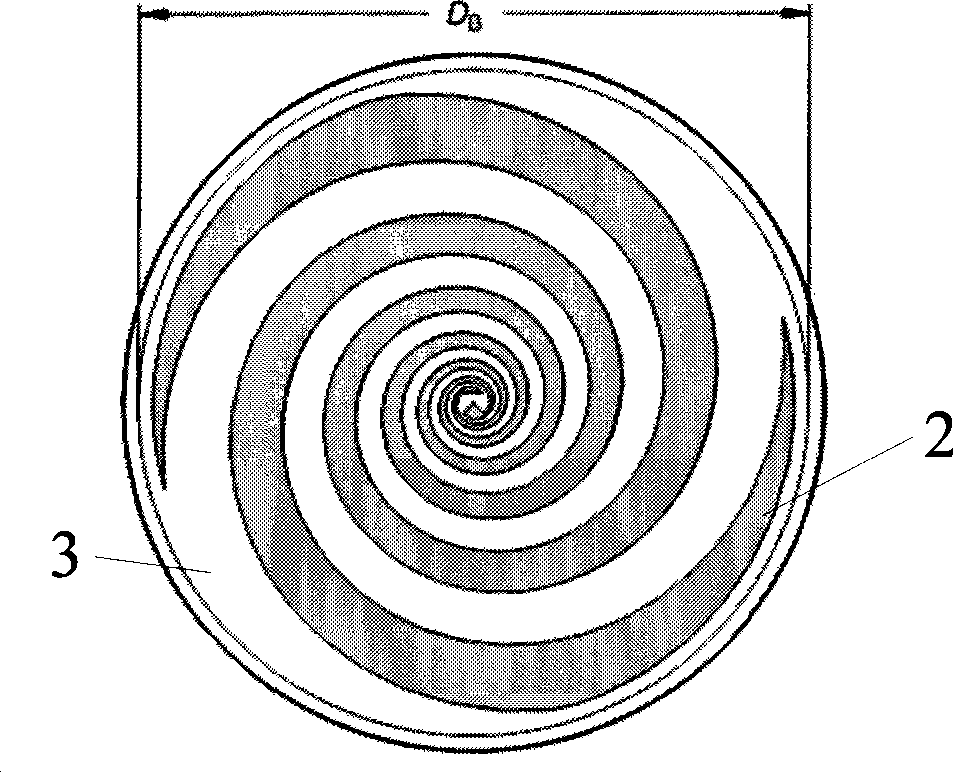
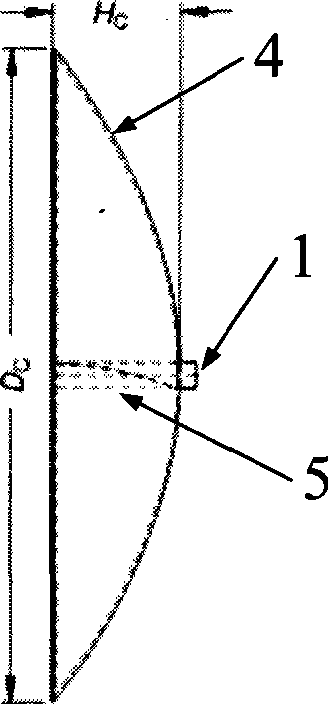
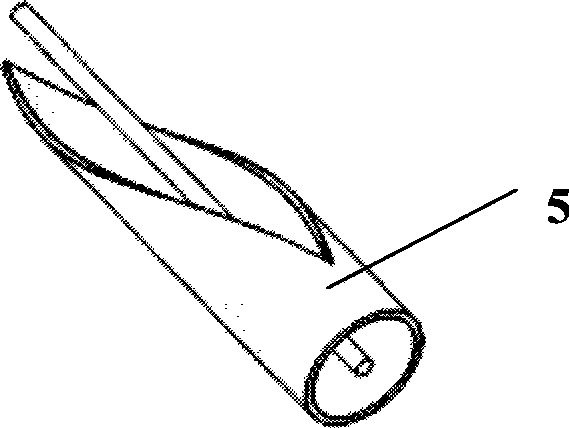
[0017] Such as figure 1 and figure 2 As shown, this embodiment includes: an input and output port 1 , a planar helical antenna 2 , a dielectric plate 3 , a metal back cavity 4 , and an involute coaxial balun wire 5 . The planar helical antenna 2 is a metal patch calculated by the spiral equation and is located on the front of the dielectric plate 3. The metal back cavity 4 is a parabolic curved surface and is located on the back of the dielectric plate 3. The inner and outer conductors of the involute coaxial balun line 5 are respectively connected to the plane spir...


PUM


Abstract

The invention relates to an ultra-wideband planar spiral antenna with a back cavity in the technical field of the wireless communication. The antenna comprises an input and output port, an involute coaxial balun line, a planar spiral antenna, a medium plate and a metallic back cavity, wherein the planar spiral antenna is a metallic patch calculated by a spiral equation, and positioned on the face of the medium plate; the metallic back cavity is a curved surface of a paraboloid and positioned on the back surface of the medium plate; the internal conductor and the external conductor of the involute coaxial balun line are respectively connected with the two arms of the planar spiral antenna; the core of the input and output port is connected with the internal conductor of the coaxial balun line. The standing wave ratio of the ultra-wideband planar spiral antenna is smaller than two within the range of 0.36-6.83GHz, and the antenna gain is about 10dB within the range of 2-6GHz. Therefore the ultra-wideband planar spiral antenna is an antenna with high gain and ultra wideband; the ultra-wideband planar spiral antenna also has the advantages of simple structure and low section.

Description

technical field [0001] The invention relates to an antenna used in the technical field of communication, in particular to an ultra-wideband planar helical antenna with a cavity back. Background technique [0002] The rapid development of wireless communication makes people put forward higher requirements for high-speed wireless communication. As an emerging short-distance wireless communication technology, UWB has many outstanding advantages such as high transmission rate, low power consumption, good security, strong anti-multipath ability and low cost. It has attracted unprecedented attention and is a highly competitive technology. One of the most powerful and promising technologies. After the FCC (Federal Communications Commission of the United States) released the license-free use of ultra-wideband (frequency band 3.1G ~ 10.6GHz) in 2002, ultra-wideband technology quickly became a hot spot in the research and development of international wireless communications, and led ...

Claims


Application Information

Patent Timeline
Patent Type & Authority Applications(China)
IPC IPC(8): H01Q1/38H01Q13/08H01Q19/12
Inventor 金荣洪耿军平劳佳叶声李忞詝
Owner SHANGHAI JIAO TONG UNIV
Why Eureka
Try Eureka