Claw pole type motor and pump

一种爪极式、爪形磁极的技术,应用在爪极式电机领域,能够解决损坏铁心等问题,达到抑制损坏、节约材料成本、加宽流路的效果

Inactive Publication Date: 2009-03-25
MATSUSHITA DENKO KK
View PDF1 Cites 7 Cited by
  • Summary
  • Abstract
  • Description
  • Claims
  • Application Information

AI Technical Summary

Problems solved by technology

While material cost can be saved by removing unnecessary parts, it is undesirable if the result is to damage the function of the core as a magnetic circuit

Method used


Image

  • Claw pole type motor and pump
  • Claw pole type motor and pump
  • Claw pole type motor and pump

Examples


no. 1 example

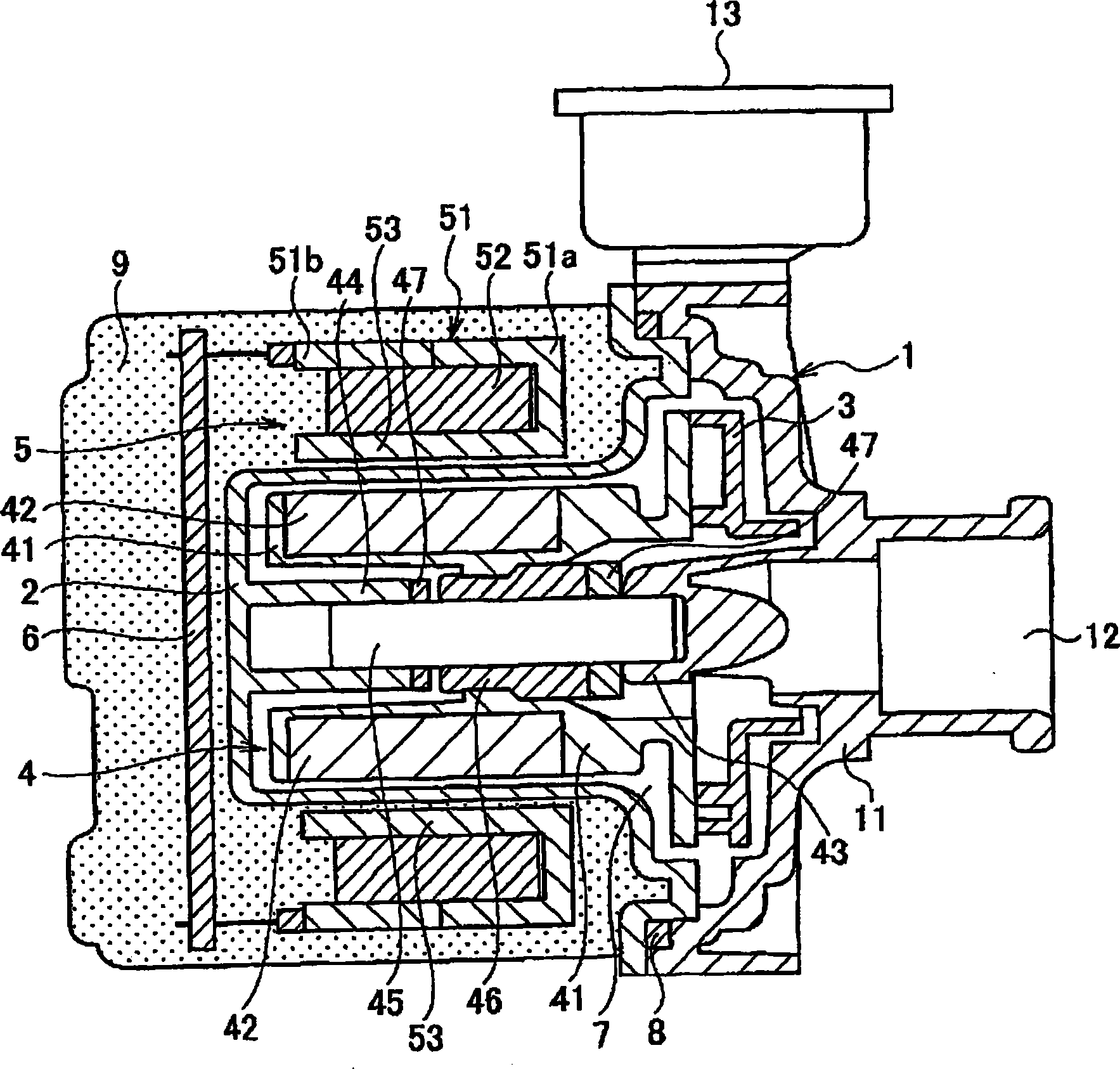
[0026] figure 1 is a sectional view of the pump according to the first embodiment of the present invention. This pump uses a claw-pole motor as its driving power source, and is mainly composed of a pump casing 1 , a partition 2 , an impeller 3 , a rotor 4 , a stator 5 , and a control circuit board 6 .

[0027] The pump housing 1 and the partition 2 are connected together to define a pump chamber 7 . A sealing element 8 is arranged in the connecting portion of the pump housing 1 and the partition 2 to ensure the liquid tightness of the pump chamber 7 . The impeller 3 and the rotor 4 are rotatably housed in the pump chamber 7 in a state of being integral with each other. The stator 5 is arranged around the rotor 4 in facing relationship with the rotor 4 with the partition 2 interposed therebetween, thereby forming a so-called inner rotor structure. The entire part of the pump except the pump housing 1 is coated with molding resin 9 . In other words, the partition 2 , the sta...

no. 2 example

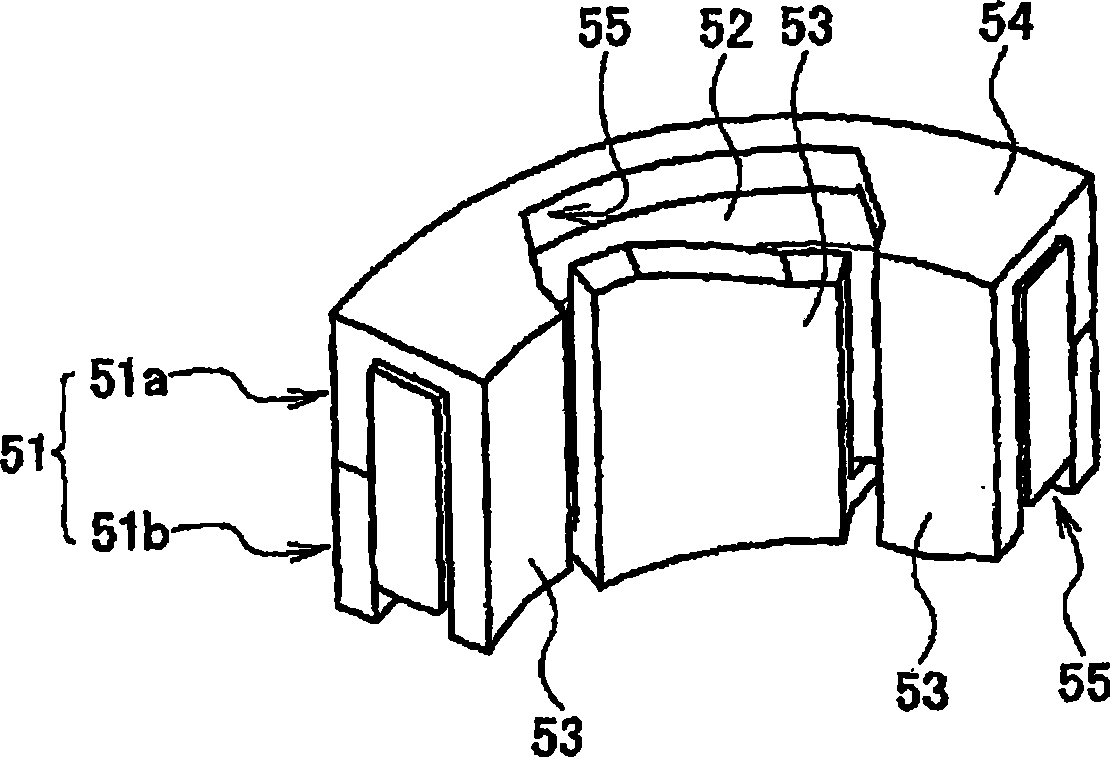
[0046] Figure 6A and 6B is a schematic perspective view of a stator 5 according to a second embodiment of the present invention, which shows the same as that of the first embodiment Figure 3A and 3B Corresponding. The pump of the second embodiment differs from the pump of the first embodiment in the structure of the stator 5 . The same parts as in the first embodiment are denoted by the same reference numerals, and redundant descriptions are omitted. Those differences are highlighted below.

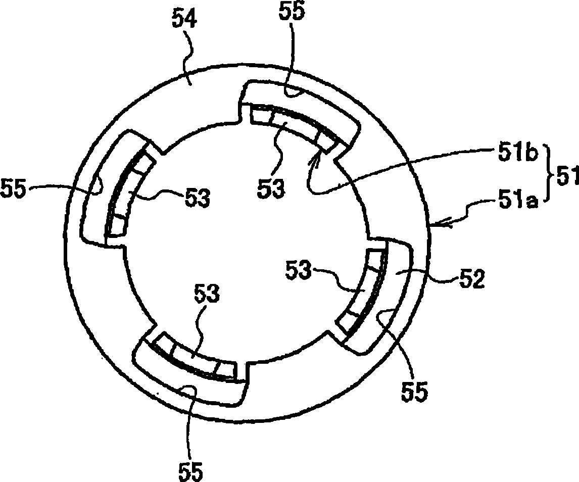
[0047] Like the first embodiment, the stator 5 includes an annular core 51 including a yoke and a plurality of claw poles 53 and an annular coil 52 housed in the core 51 . The yoke has a substantially C-shaped cross-sectional shape that is opened on an inner peripheral surface opposite to the rotor 4 . The yoke has a cylindrical side wall portion 56 for covering the outer peripheral surface of the loop coil 52 , and a pair of end surface portions 54 between which the loop coil 52 ...


PUM


Abstract

A claw pole type motor includes a rotor having a magnet arranged on an outer circumferential surface thereof and a stator including an annular iron core and an annular coil received within the iron core. The iron core includes a yoke portion opened in an inner circumferential surface opposite to the rotor, a plurality of upper claw-shaped magnetic poles and a plurality of lower claw-shaped magnetic poles which are arranged along an inner circumferential surface of the annular coil. The upper / lower claw-shaped magnetic poles are curved to extend axially downwardly / upwardly from an upper / lower inner edge of the yoke portion, respectively. The upper and the low claw-shaped magnetic poles are alternately arranged along a circumferential direction of the iron core. The yoke portion has cutout portions formed in non-magnetic path regions which do not include magnetic paths through which magnetic flux flows between neighboring claw-shaped magnetic poles across the annular coil.

Description

technical field [0001] The invention relates to a claw pole motor and a pump using the motor as a driving power source. Background technique [0002] A known pump for sucking and discharging, for example, liquid employs a claw-pole motor having claw-shaped magnetic poles as a motor for rotationally driving an impeller (see, for example, Japanese Patent Laid-Open Application No. 2003-505648). The claw pole motor is simple in structure, and thus has advantages in high productivity and low production cost. [0003] In general, a stator of a claw pole type motor is formed of a core having a plurality of claw-shaped magnetic poles arranged in a circumferential direction and an annular coil housed in the core. The core serves as the magnetic circuit and is formed from a moulding. Although material cost can be saved by removing unnecessary parts, it is not desirable if the result is to damage the function of the core as a magnetic circuit. Contents of the invention [0004] In...

Claims


Application Information

Patent Timeline
Patent Type & Authority Applications(China)
IPC IPC(8): H02K1/12H02K15/02
CPCH02K21/145H02K11/0073H02K15/12H02K7/14H02K5/128H02K2211/03H02K1/145H02K11/33F04D13/06
Inventor 桥本俊治井上弘干薮内英一西方政昭末松真二
Owner MATSUSHITA DENKO KK
Why Eureka
Try Eureka