Ultrasonic endoscope

A technology of ultrasound and endoscopy, applied in the field of ultrasound endoscopy, can solve problems such as blocking and obstructing observation

Active Publication Date: 2009-03-25
OLYMPUS CORP
View PDF2 Cites 8 Cited by
  • Summary
  • Abstract
  • Description
  • Claims
  • Application Information

AI Technical Summary

Problems solved by technology

Therefore, in optical observation, there may be a problem that a part of the observation field of view is blocked by the ultrasonic signal transmitting and receiving unit, or that a shadow of the ultrasonic vibrator unit is generated during optical imaging, which hinders observation.
In addition, in ultrasonic observation, there may be a problem that an artifact may appear in the ultrasonic image due to the reflection of ultrasonic waves by the air and water nozzles, etc.

Method used


Image

  • Ultrasonic endoscope
  • Ultrasonic endoscope
  • Ultrasonic endoscope

Examples


Embodiment Construction

[0024] Hereinafter, embodiments of the present invention will be described in detail with reference to the drawings.

[0025] refer to Figure 1 to Figure 1 0, describe in detail the implementation of the present invention.

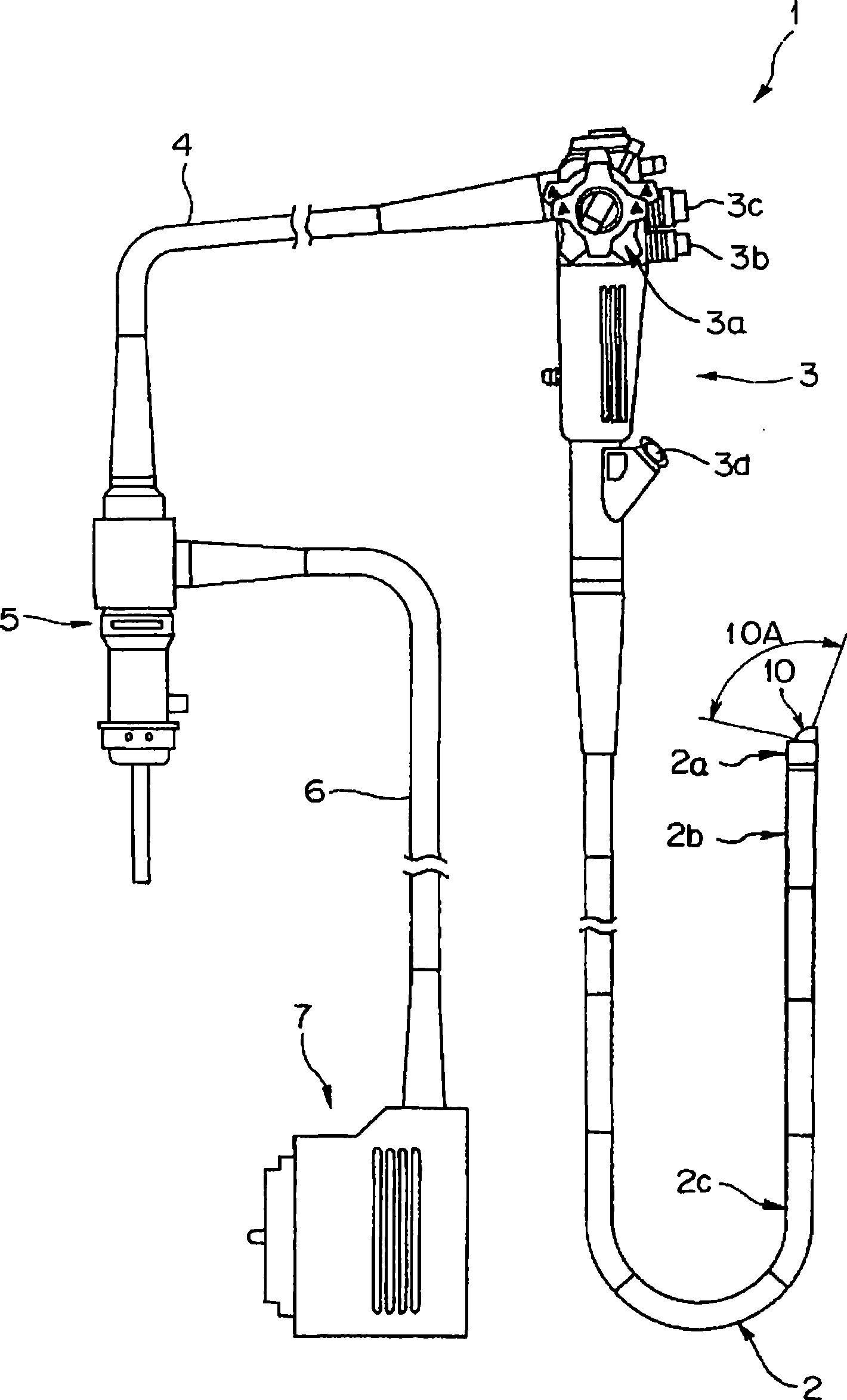
[0026] Such as figure 1 As shown, the ultrasonic endoscope 1 of this embodiment includes: an elongated insertion part 2 inserted into the body cavity, an operation part 3 provided at the base end of the insertion part 2, a universal Connect the cable 4. An endoscope connector 5 is provided at the proximal end of the universal connection cable 4 . An ultrasonic cable 6 extends from the side of the endoscope connector 5 . An ultrasonic connector 7 is provided at the proximal end of the ultrasonic cable 6 .

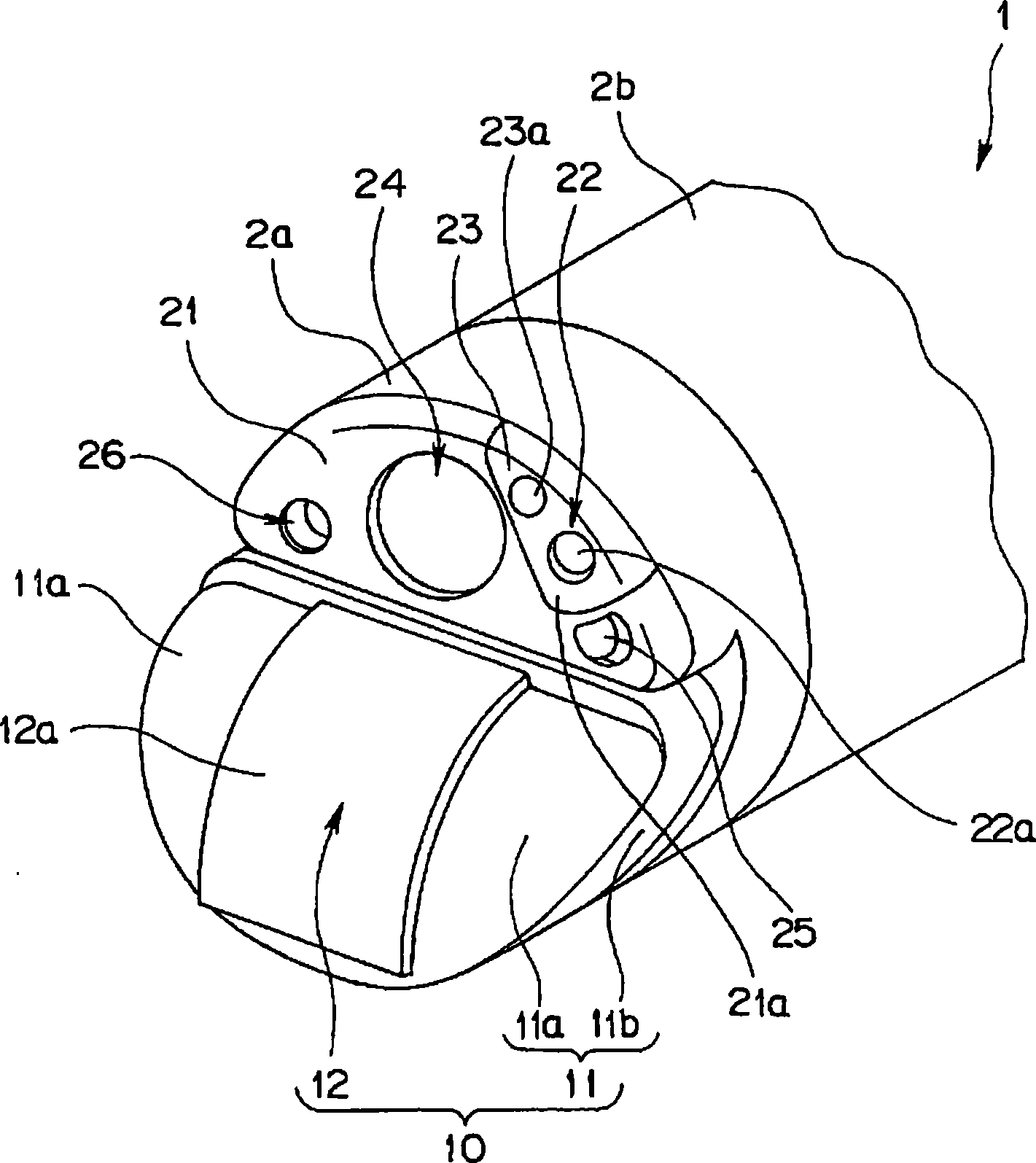
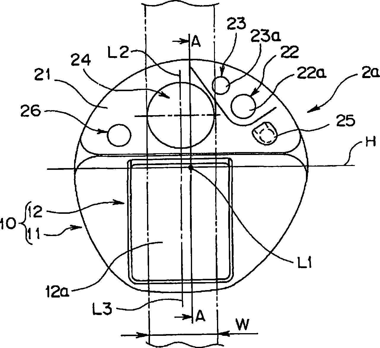
[0027] The insertion part 2 is in the shape of a long strip extending from the base end of the bending part 2b to the front end of the operation part 3, sequentially connecting the front end hard part 2a formed by a hard member, the bending part 2b...


PUM


Abstract

An ultrasound endoscope including, at a distal end of an insertion portion to be inserted to a body cavity, a distal rigid portion arranged forward of a flexible tube portion, an ultrasound transducer portion for scanning a plane which is parallel to forward side of a longitudinal center axis L1 of the distal rigid portion, and a treatment instrument insertion channel port opening in a distal-side end face of the distal rigid portion, with a longitudinal center axis L4 being parallel to the longitudinal center axis L1 of the distal rigid portion.

Description

technical field [0001] The present invention relates to an ultrasonic endoscope having an observation optical system, a treatment tool outlet, and a convex ultrasonic signal transmitting and receiving unit at the front end of an insertion unit. Background technique [0002] Conventionally, an ultrasonic endoscope having a convex ultrasonic signal transmitting and receiving unit is known as an ultrasonic endoscope for performing ultrasonic diagnosis in a body cavity. The convex ultrasonic signal transmitting and receiving part is formed by arranging a plurality of transducer arrays in a convex arc shape. [0003] As an ultrasonic endoscope having a convex ultrasonic signal transmitting and receiving unit, there is, for example, an ultrasonic endoscope disclosed in Japanese Patent Application Laid-Open No. 8-131442. The distal end hard part of this ultrasonic endoscope has an observation optical system, and also has an ultrasonic signal transmitting and receiving part with an...

Claims


Application Information

Patent Timeline
Patent Type & Authority Applications(China)
IPC IPC(8): A61B8/12
CPCA61B1/00094A61B1/00087A61B1/0008A61B1/018A61B8/12A61B1/00096A61B8/445
Inventor 儿玉启成中里威晴
Owner OLYMPUS CORP
Why Eureka
Try Eureka