Liquid constant-rate emitting apparatus and method of liquid constant-rate emission

A technology for discharging devices and liquids, which is applied in chemical instruments and methods, feeding devices, electrochemical generators, etc., and can solve the problems of needing a storage pump and increasing the size of the cost-increasing device.

Inactive Publication Date: 2009-03-25
ROHM CO LTD
View PDF3 Cites 5 Cited by
  • Summary
  • Abstract
  • Description
  • Claims
  • Application Information

AI Technical Summary

Problems solved by technology

It is preferable to use a pump to control (limit) the amount of water delivered, but this requires a space for housing the pump and a drive mechanism, which leads to an increase in cost and an increase in the size of the device

Method used


Image

  • Liquid constant-rate emitting apparatus and method of liquid constant-rate emission
  • Liquid constant-rate emitting apparatus and method of liquid constant-rate emission
  • Liquid constant-rate emitting apparatus and method of liquid constant-rate emission

Examples


no. 1 approach

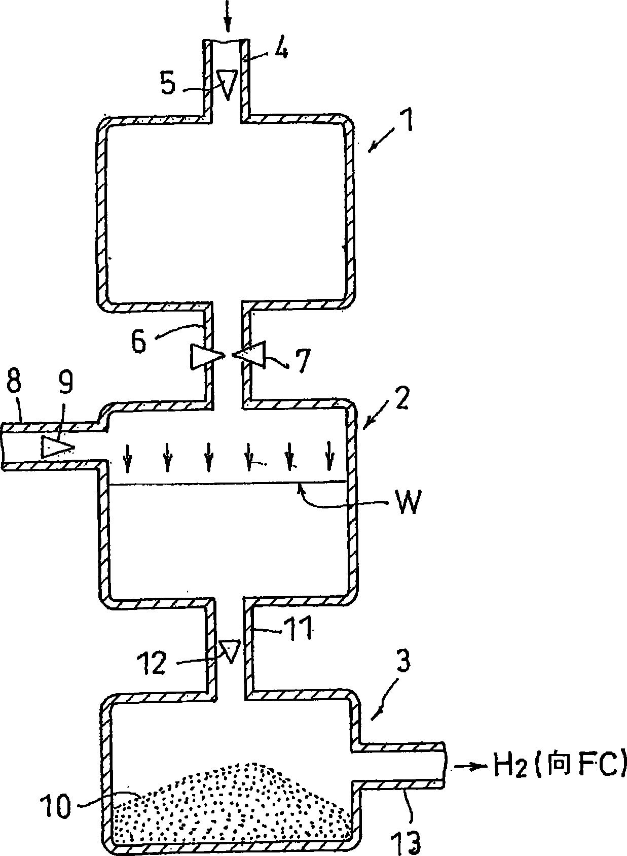
[0060] figure 1 It is a conceptual diagram showing the structure of the quantitative liquid discharge device of the first embodiment. This liquid quantitative discharge device has a gas storage container 1 and a liquid storage container 2 . Compressed air is stored in the gas storage container 1 . In addition, other gases such as nitrogen may be used instead of air. An introduction pipe 4 and a check valve 5 are provided on the upper wall of the gas storage container 1 , and air is introduced into the gas storage container 1 through the introduction pipe 4 . The amount of introduced air is, for example, about 3 cc, and it is stored in a state compressed to about 3 atmospheres. Any type can be applied as the check valve 5, but it is preferable to have a bird's beak (くちばし) that opens when the pressure on the primary side is higher than the pressure on the secondary side and closes when the pressure on the primary side is lower than the pressure on the secondary side, in addit...

no. 2 approach

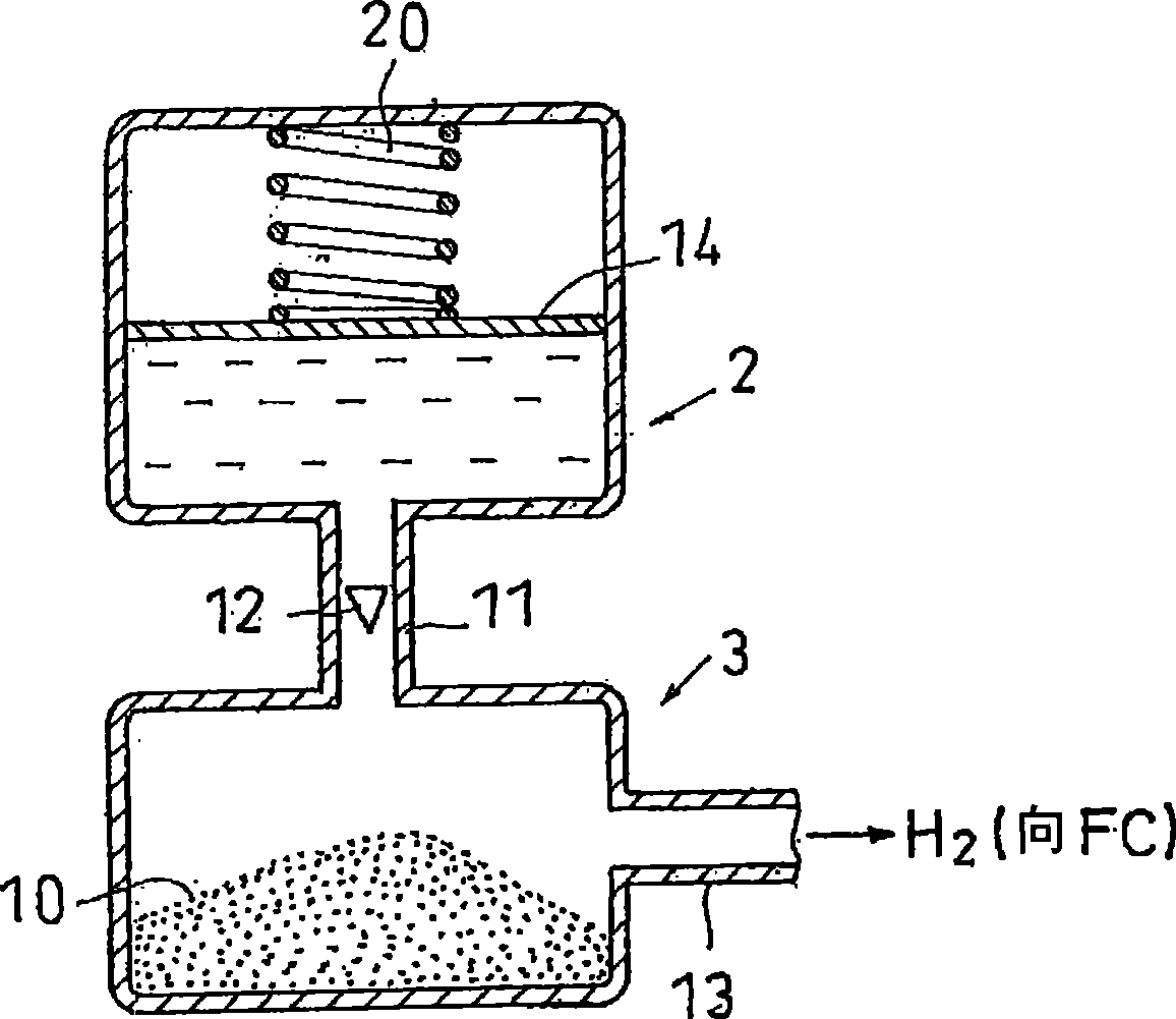
[0068] Next, according to figure 2 The configuration of the liquid quantitative discharge device according to the second embodiment will be described. with figure 1 The different points will be explained centering on it. figure 2 In the liquid storage container 2, a movable partition wall portion 14 arranged to partition the inside of the liquid storage container 2 is provided. As shown in the drawing, the movable partition wall part 14 is arranged above the water surface W, and the surface on the lower side of the movable partition wall part 14 and the water surface W is pressed by compressed air. By providing the movable partition wall portion 14, the water surface W can be squeezed more uniformly, and water can be discharged in a more stable quantity in a more stable state.

[0069] The movable partition wall portion 14 is a plate-shaped member, and can be formed of an appropriate material, for example, glass with good sliding properties can be used. In addition, by p...

no. 3 approach

[0074] Next, according to Figure 5 , Figure 6 Results of the liquid quantitative discharge device of the third embodiment will be described. The description will focus on points different from the first embodiment and the second embodiment. The structure of the injection valve B for injecting compressed air into the gas storage container 1 will be described. When using a liquid quantitative discharge device for a fuel cell of a portable device, it is preferable that the liquid quantitative discharge device be downsized, and the filling valve B itself is preferably as small as possible. In addition, in the case of the above-mentioned application, the compressed air to be injected is 2 to 3 cc and the pressure is about 0.3 to 0.5 MPa.

[0075] As the injection valve B, a valve having the same structure as the valve for injecting gas into the gas burner can be used. Its structure is as Figure 6 as shown, Figure 6 (a) shows the state where the valve is closed, and (b) sh...


PUM


Abstract

A liquid constant-rate emitting apparatus that in the event of delivering a liquid, such as water, from a liquid accommodating container, even when the amount thereof is small, is capable of constant-rate delivery thereof. There is provided an apparatus comprising liquid accommodating container (2) for water accommodation; water lead-out pipe (11) for water emission from the liquid accommodating container (2); gas accommodating container (1) for compressed air accommodation; and introduction pipe (6) for feeding of the compressed air within the gas accommodating container (1) into the liquid accommodating container (2), so that constant-rate water emission from the water lead-out pipe (11) is attained by application of the compressed air to the liquid within the liquid accommodating container (2).

Description

technical field [0001] The present invention relates to a liquid quantitative discharge device and a liquid quantitative discharge method capable of quantitatively supplying a small amount of liquid. Background technique [0002] Compared with other power generation systems, fuel cells are attracting attention as an energy source that has high power generation efficiency and does not generate air pollutants. In a hydrogen supply type fuel cell, air (oxygen) is supplied to the cathode and hydrogen is supplied to the anode in order to generate electricity. Hydrogen becomes hydrogen ions and electrons through a mediator reaction with the anode, and the hydrogen ions move in the electrolyte, and react with oxygen through a cathode mediator reaction to become water. Electrons, on the other hand, propagate in the external circuit, moving towards the cathode. Electric energy is generated by the movement of the electrons. [0003] As described above, fuel such as hydrogen needs t...

Claims


Application Information

Patent Timeline
Patent Type & Authority Applications(China)
IPC IPC(8): B01J4/00B01J4/02C01B3/08H01M8/06
CPCB01J4/008H01M8/04179Y02E60/362Y02E60/324Y02E60/50H01M8/0662H01M8/04186C01B3/065B01J4/02H01M8/06Y02E60/36H01M8/04
Inventor 杉本正和矢野雅也杉田泰一
Owner ROHM CO LTD
Why Eureka
Try Eureka