Apparatus for blow moulding containers, comprising transport elements with two gripper arms

A blow molding, blow molding device technology, applied in the direction of household components, applications, household appliances, etc., to achieve the effect of simple controllability

Active Publication Date: 2009-03-25
KHS GMBH
View PDF4 Cites 9 Cited by
  • Summary
  • Abstract
  • Description
  • Claims
  • Application Information

AI Technical Summary

Problems solved by technology

However, the grippers used hitherto were not able to meet all the requirements imposed on the protected and at the same time permissible manipulation of the preforms

Method used


Image

  • Apparatus for blow moulding containers, comprising transport elements with two gripper arms
  • Apparatus for blow moulding containers, comprising transport elements with two gripper arms
  • Apparatus for blow moulding containers, comprising transport elements with two gripper arms

Examples


Embodiment Construction

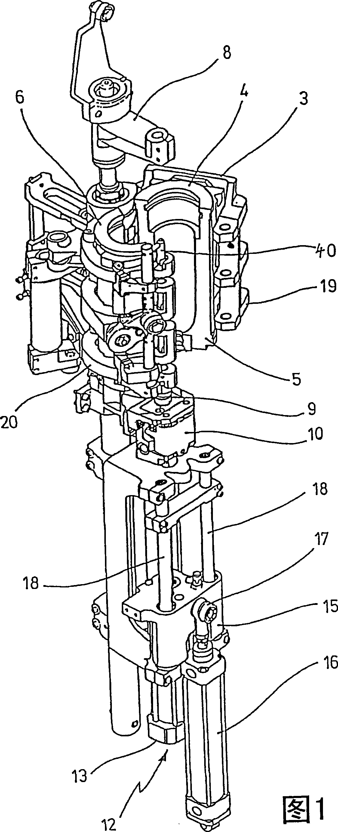
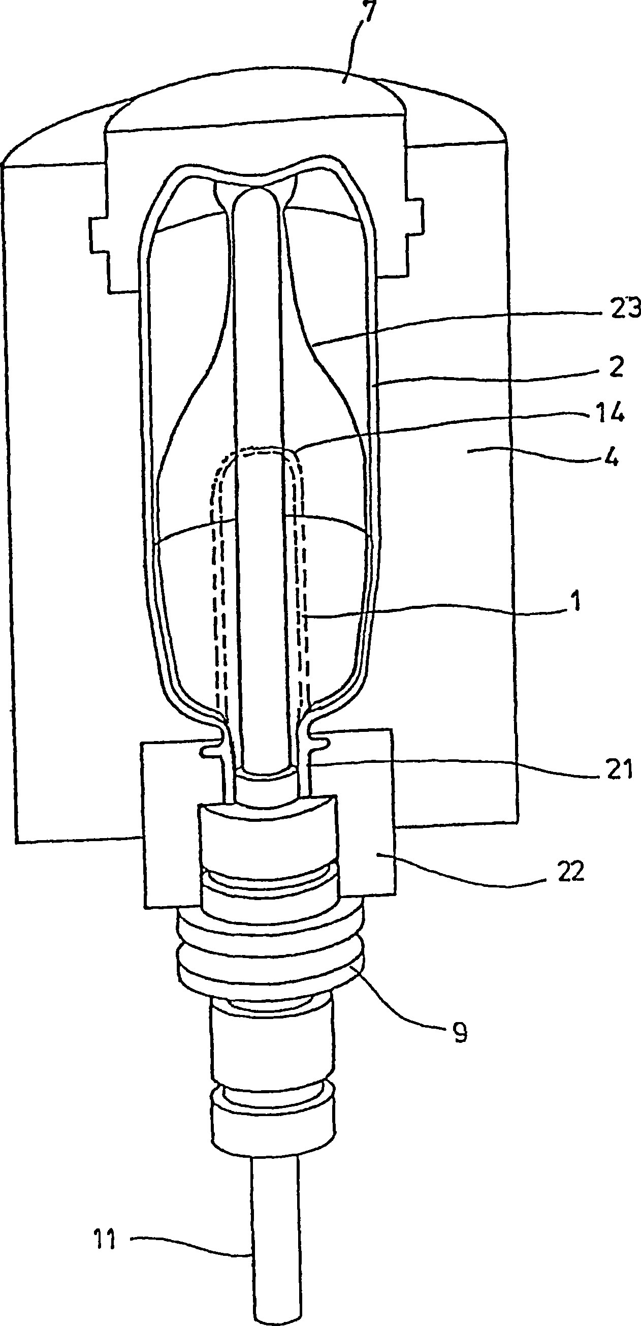
[0035] In Figure 1 and figure 2 The principle structure of a device for forming preforms 1 into containers 2 is shown in . It can be arranged as shown, or rotated 180° in a vertical plane.

[0036] The device for molding said container 2 essentially comprises a blow molding station 3 provided with a blow mold 4 into which the preform 1 can be inserted. The preform 1 may be an injection molded part made of polyethylene terephthalate. In order to allow the preform 1 to be inserted into the blow mold 4 and the finished container 2 to be removed, the blow mold 4 consists of mold halves 5, 6 and a bottom part 7 which can be lifted by a The device 8 is positioned. The preform 1 can be held in place by a holding element 9 in the region of the blow molding station 3 . It is possible, for example, to insert the preform 1 directly into the blow mold 4 by means of pliers or another operating mechanism.

[0037] For the introduction of compressed air, a connecting piston 10 is arrang...


PUM


Abstract

The apparatus serves for blow moulding containers. Preforms of a thermoplastic material are heated in the region of a heating zone and subsequently transferred to a blow moulding device. The blow moulding device is provided with at least one blow moulding station for transforming the preforms into the containers. Provided for handling the preforms is a gripper-like transporting element (41) with two gripper arms (45, 46), which are arranged pivotably in relation to a gripper carrier (42). Each of the gripper arms can be pivoted by means of at least one lever and is coupled with a central element (49). The central element is arranged at least partly between the gripper arms. Each of the gripper arms is resiliently clamped with respect to the central element by at least one spring (56, 57).

Description

technical field [0001] The invention relates to a device for blow molding containers, which has a heating zone for heating preforms made of thermoplastic material and is provided with a blow molding device with at least one device for making the preforms Blow molding station for forming preforms into containers; for manipulating the preforms, at least one tong-like transport element with two tong arms which are pivotably arranged relative to a tong carrier is provided. Background technique [0002] During container molding by means of blowing pressure, preforms made of thermoplastic material, for example PET (polyethylene terephthalate), are conveyed inside the blow molding machine to different processing stations. Usually such a blow molding machine has a heating device and a blow molding device, in the region of which the previously heated preform is expanded by biaxial orientation to form a container. This expansion takes place by means of compressed air introduced into...

Claims


Application Information

Patent Timeline
Patent Type & Authority Applications(China)
IPC IPC(8): B29C49/42B29C49/06B29C49/12B29C49/36B29C49/64
CPCB29C49/421B29L2031/7158B29C49/6418B29B2911/14106B29B2911/1402B29K2067/00B29C49/4205B29B2911/14133B29B2911/1404B29C49/06B29C49/12B29C33/26B29B2911/14033B29C49/36B29B2911/14026B29C2949/26B29C2949/28B29C2949/24B29C2949/22B29C2949/3024B29C2949/3032B29C49/42069B29C49/42073B29C49/42087B29C2949/0715
Inventor M·林克M·利岑贝格R·鲍姆加特F·莱温
Owner KHS GMBH
Why Eureka
Try Eureka