Method and apparatus for eliminating directly coupling signal of induction logging tool

An induction logging and signal technology, applied in electrical/magnetic detection for logging records, earthwork drilling, borehole/well components, etc., can solve the difficulty of phase reference signal, direct coupling signal mixing, and consistency And other issues

Inactive Publication Date: 2009-04-01
CHINA NAT OFFSHORE OIL CORP +1
View PDF1 Cites 21 Cited by
  • Summary
  • Abstract
  • Description
  • Claims
  • Application Information

AI Technical Summary

Problems solved by technology

However, since the voltage induced by the receiving coil is very small, it needs to be amplified before phase-sensitive detection can be performed, and the A/D conversion, amplifier (for amplifying the received signal) and the receiving coil itself will generate a phase shift for the induced voltage of the receiving coil, while the transmitting circuit The phase shift with the transmitting coil also makes it difficult for the phase of the phase reference signal to be consistent with the phase of the transmitting current, so the original phase relationship has been broken due to the phase shift of

Method used


Image

  • Method and apparatus for eliminating directly coupling signal of induction logging tool
  • Method and apparatus for eliminating directly coupling signal of induction logging tool
  • Method and apparatus for eliminating directly coupling signal of induction logging tool

Examples


Embodiment Construction

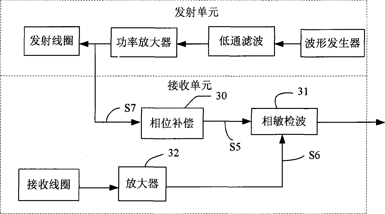
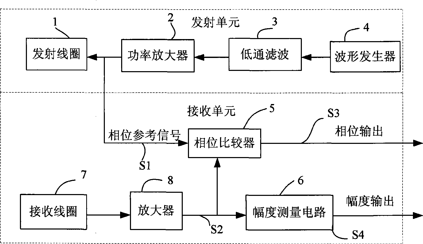
[0036] The induction logging instrument includes a transmitting coil and a receiving coil, and the induced voltage signal of the receiving coil can be decomposed into a direct coupling signal and a secondary induction signal. The method for eliminating the direct coupling signal of the induction logging instrument in the present invention includes the following steps:

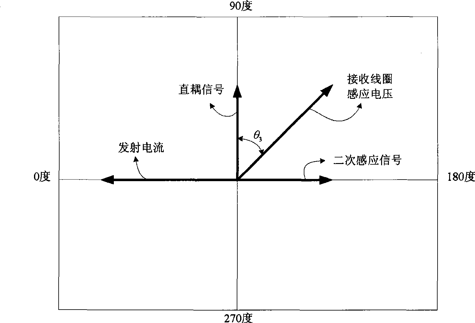
[0037]Step 1. Increase the direct coupling signal in the induction voltage of the receiving coil in the air until the secondary induction signal is sufficiently small relative to the direct coupling signal, and measure the induction voltage of the receiving coil (which can be considered as a direct coupling signal at this time) and the transmitted signal. The phase difference θ of the current or voltage signal of the coil 1 ;

[0038] Measuring theta in air 1 It is because the secondary induction signal in the measurement signal in the air is very small, so after increasing the direct coupling signal, the seco...


PUM


Abstract

The invention provides a method for eliminating a direct coupling signal of a sensing logging instrument and a device thereof. A transmitting unit of the device comprises a transmitting coil; a receiving unit comprises a receiving coil, a compensating coil, a phase comparator and an amplitude measuring circuit, wherein, the input signals of the phase comparator are respectively a current or voltage signal passing through the transmitting coil and the sensing voltage of the receiving coil and used for measuring the sensing voltage of the receiving coil and the phase difference of the current or voltage signal passing through the transmitting coil under the following two conditions: the portion of the direct coupling signal of the sensing voltage of the receiving coil is increased in the air until a secondary sensing signal is small enough relative to the direct coupling signal, and the phase difference Theta 1 is measured; under normal condition, the phase difference Theta 2 is measured; the amplitude measuring circuit is used for measuring the amplitude value A of the sensing voltage of the receiving coil in a stratum under normal condition; and the formulas that R equals to A multiplied by sin (Theta 3) and Theta 3 equals to Theta 2 minus Theta 1 are utilized to calculate the amplitude value of the secondary sensing voltage. The method and the device can eliminate the errors caused by the phase displacement of the instrument and effectively eliminate the direct coupling signal.

Description

technical field [0001] The invention belongs to the technical field of induction well logging, in particular to a method and a device for eliminating direct coupling signals in induction well logging instruments. Background technique [0002] In electromagnetic induction logging, the voltage signal induced by the receiving coil can be divided into two parts: one part is the secondary induced voltage generated by the eddy current in the formation to the receiving coil, called the secondary induced signal, which is sensitive to the formation conductivity and is most useful signal; the other part is the voltage directly coupled from the transmitting coil to the receiving coil, called the direct coupled signal, which is not sensitive to the conductivity of the formation and is a useless signal. Since the direct coupling signal is much larger than the secondary induction signal, it is necessary to remove the direct coupling signal to extract the secondary induction signal. [00...

Claims


Application Information

Patent Timeline
IPC IPC(8): E21B49/00G01V3/28
Inventor 孙向阳李爱勇魏少华聂在平管国云罗曦
Owner CHINA NAT OFFSHORE OIL CORP
Why Eureka
Try Eureka