Slide holding device of rotary compressor and control method thereof

A rotary compressor and retaining device technology, which is applied to rotary piston machines, rotary piston pumps, rotary piston/swing piston pump components, etc., and can solve problems such as damage to sliding vanes, unstable vibration of sliding vanes, etc. , to prolong the service life, prevent damage to the slide, and prevent the sound of the slide from beating

Active Publication Date: 2011-05-25
GUANGDONG MEIZHI COMPRESSOR
View PDF1 Cites 0 Cited by
  • Summary
  • Abstract
  • Description
  • Claims
  • Application Information

AI Technical Summary

Problems solved by technology

Such as Japanese patent: patent publication No. 1-247786, i.e. patent document 1, and patent publication No. 2004-301114 communique, i.e. the design problem that occurs when the slide plate is kept away from the piston disclosed in patent document 2. It is difficult to equip large devices such as magnets or tension springs in the cavity, and when the compression of the cylinder cavity stops and the moment the suspension is released, the slide will have unstable vibration problems; especially the unstable vibration of the slide will bring The following reliability problems: slide beating sound caused by the collision between the front end of the slide and the outer circumference of the piston, and the resulting damage to the slide

Method used


Image

  • Slide holding device of rotary compressor and control method thereof
  • Slide holding device of rotary compressor and control method thereof
  • Slide holding device of rotary compressor and control method thereof

Examples


no. 1 example

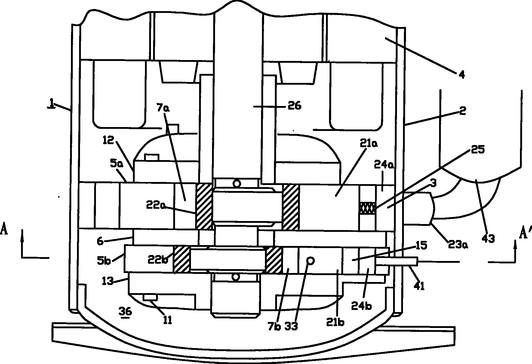
[0028] See figure 1 , Is the internal structure of the rotary compressor 1 of the present invention. The internal pressure of the sealed housing 2 is on the high-pressure side, a compression assembly 3 is provided at the lower part, and a motor 4 is provided at the upper part, and their outer diameters are fixed to the inner diameter of the housing 2. The compression assembly 3 has two cylinders, a first cylinder 5a and a second cylinder 5b. The two cylinders are separated by a central partition 6 to form a first cylinder cavity 7a and a second cylinder 7b, respectively. Wherein, the displacement of the second cylinder 5b is smaller than the displacement of the first cylinder 5a, and the method to realize this design is to change the height dimension of any cylinder.

[0029] On the upper surface of the first cylinder 5a and the lower surface of the second cylinder 5b, the main bearing 12 and the auxiliary bearing 13 are installed with screws 11 respectively. In the sealed first ...

no. 2 example

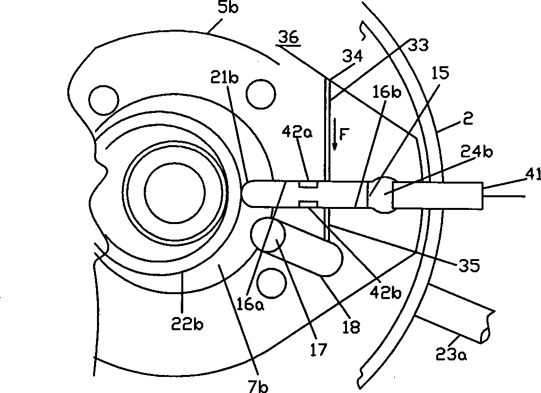
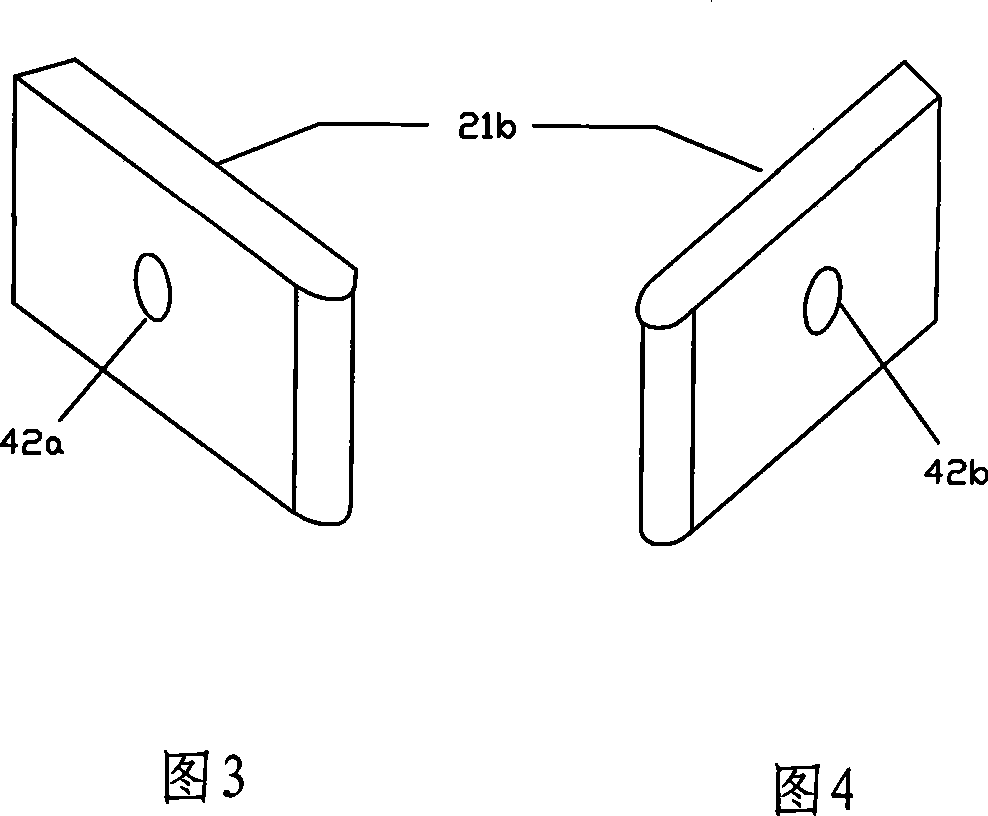
[0052] See Figure 7 In this embodiment, the design solution of the low pressure hole 35 used in the first embodiment is omitted. When the second sliding vane cavity 24b is switched to the low pressure side and the compression is stopped, in the two gaps between the second sliding vane 21b and the sliding vane groove 15, the gap between the sliding vane groove H surface 16a is affirmed by the function of the first recess 42a On the high-pressure side, the gap between the sliding vane groove L surface 16b is partially low-pressure even if there is no low-pressure hole 35, so a force F is generated. Therefore, some design schemes of rotary compressors can adopt the second embodiment.

no. 3 example

[0054] See Figure 8 with Picture 9 In this embodiment, the second recess 42b is designed to replace the low pressure hole 35 described in the first embodiment. On the side surface of the second sliding piece 21b, a bypass groove 37 opening in the second sliding piece cavity 24b communicates with the second recess 42b.

[0055] When the second sliding vane chamber 24b is switched to the high pressure side and the second cylinder chamber 7b continues to compress, the bypass groove 37 and the second recess 42b are both on the high pressure side. Because the high-pressure hole 34 and the first recess 42a are also on the high-pressure side, the force F on the side of the sliding blade is almost zero.

[0056] When the second vane cavity 24b is switched to the low pressure side, the bypass groove 37 and the second recessed portion 42b are both on the low pressure side, so the force F almost equal to that of the first embodiment is generated. Therefore, the second sliding piece 21b is...


PUM


Abstract

The invention relates to relates to a sliding vane holding device of a rotary compressor and a controlling method thereof; a motor and a compressing component connected with the motor are arranged in a sealed shell in which the pressure is a high-pressure side; the compressing component comprises two cylinders, and an intermediate baffle is arranged between the cylinders; each cylinder are held in a cylinder cavity of a circular piston which can carry out a free eccentric rotation; the sliding of a sliding vane is set in a sliding vane groove; the rear end part of the sliding vane is held in a sliding vane cavity; the sliding vane is pressed, and the front end of the sliding vane is in contact with and closely follows with the outer diameter of the circular piston, wherein, a first sliding cavity is provided with a spring connected with the sliding vane. The sliding vane holding device is characterized in that a cross hole is arranged on a second cylinder; one end of the cross hole isat the high-pressure side, and the other end of the cross hole is at the sliding groove of the second cylinder; a first concave part with a diameter more than the diameter of the cross hole is arranged on the lateral motion surface of a second sliding vane corresponding to the cross hole; a second sliding vane cavity is communicated with one end of a pressure switching pipe, and the other end of the pressure switching pipe stretches out of the shell and is communicated with a pressure switching valve.

Description

Technical field [0001] The invention relates to a rotary compressor, in particular to a sliding vane holding device of the rotary compressor and a control method thereof. Background technique [0002] In recent years, as two-cylinder rotary compressors have been applied to air conditioners, as one example, a method for stopping the compression of the cylinders to control the cooling capacity of the compressor has been disclosed. As a representative example of these cold capacity control technologies, the internal pressure of the closed sliding vane cavity or the pressure of the cylinder compression cavity is switched between low pressure and high pressure, and the sliding vane is moved away from the piston direction through the retaining device to keep the sliding vane in the direction of the piston. The inside of the sliding vane cavity and the method of releasing the hold to suspend and release the compression of the cylinder cavity have been disclosed. For example, Japanese P...

Claims


Application Information

Patent Timeline
Patent Type & Authority Patents(China)
IPC IPC(8): F04C18/356F04C29/00F04C28/00
Inventor 小津政雄
Owner GUANGDONG MEIZHI COMPRESSOR
Why Eureka
Try Eureka