Cursor positioning method for handhold camera

A cursor positioning and camera technology, applied in user/computer interaction input/output, computer components, mechanical mode conversion, etc., can solve problems such as excessive movement, difficult cursor, and difficulty in directly operating the computer that plays the slideshow, etc., to achieve Accurate positioning, avoiding the effect of inaccurate positioning

Inactive Publication Date: 2009-04-01
View PDF0 Cites 6 Cited by
  • Summary
  • Abstract
  • Description
  • Claims
  • Application Information

AI Technical Summary

Problems solved by technology

[0003] Generally, the mouse must be used on a fixed plane (usually a desktop), but in some specific occasions, there is a problem that the mouse cannot be used. PowerPoint) to play slides, the speaker usually uses a laser pointer to explain the content of the slides on the podium, it is difficult to directly operate the computer that plays the slides, in most cases, the speaker needs to operate through another person However, this kind of computer not only requires the speaker and the computer operator to coordinate the operation of the slide file with gestures, gestures (such as nodding) or words, but it is difficult for the speaker to direct the operation of the computer except for the routine operation of page jumping. The user can perform operations that need to be clicked with the cursor, such as clicking the hyperlink function in the slideshow, or selecting part of the text to display it in reverse video, etc.
[0004] Although there are products on the market that combine a laser pointer and a shake-controlled mouse, the laser pointer held by the speaker

Method used


Image

  • Cursor positioning method for handhold camera
  • Cursor positioning method for handhold camera
  • Cursor positioning method for handhold camera

Examples


Embodiment Construction

[0028] Now with regard to the preferred embodiment of the present invention, with reference to the accompanying drawings, the detailed description is as follows.

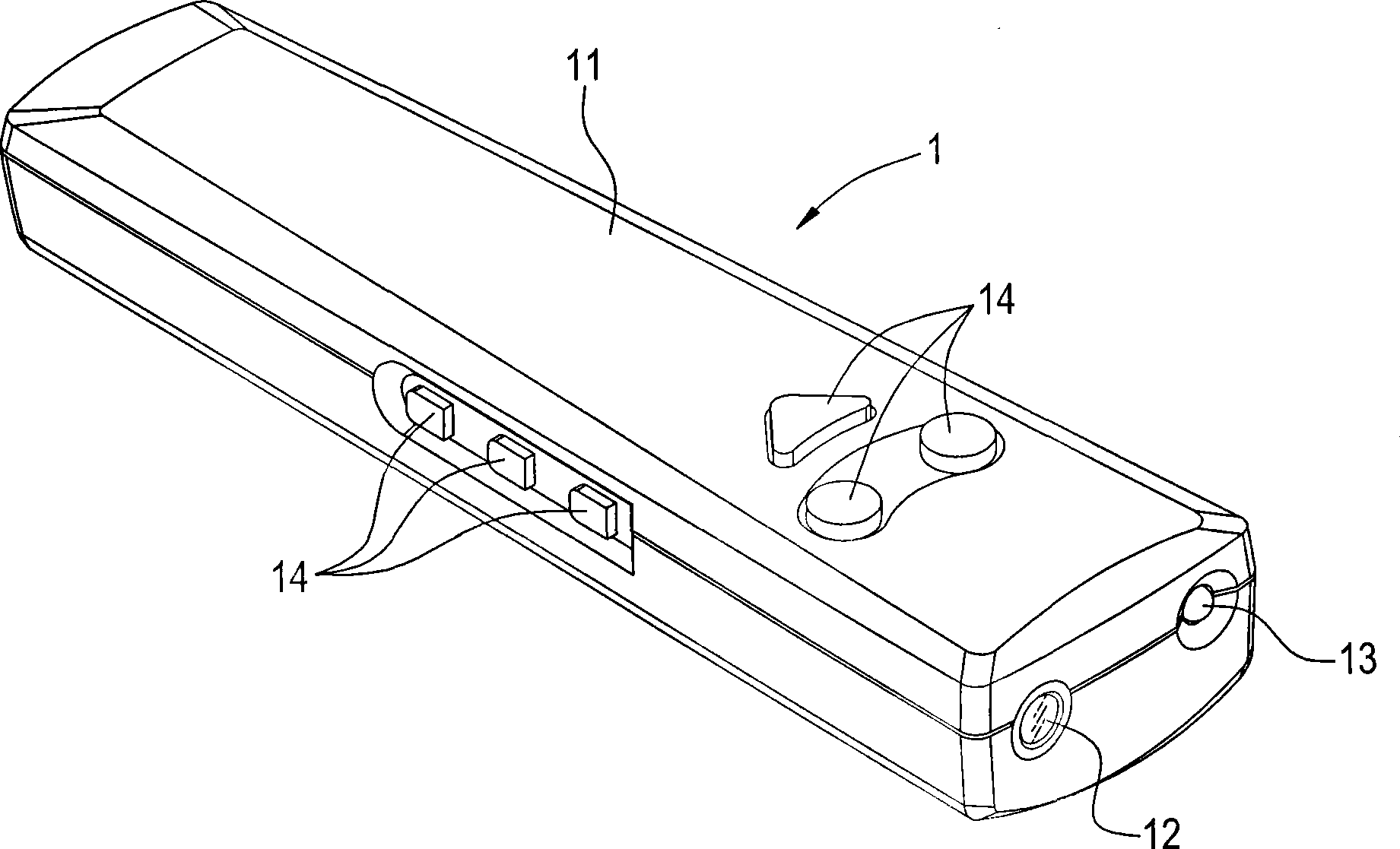
[0029] See first figure 1 , which is a three-dimensional schematic view of the handheld camera of the present invention. The handheld camera 1 is installed in a housing 11 suitable for holding a digital camera 12. The housing 11 is preferably an elongated body, and is particularly preferably compatible with The laser guide 13 is installed in the same housing 11, and the luminous body of the laser guide 13 and the lens of the digital camera 12 are all located on the same end face of the housing 11, so that the hand-held camera 1 can also have a laser The guiding function is more conducive to the user's operation, but the digital camera 12 and the laser guide 13 are only installed in the same casing 11, and the two operate and control independently. The surface of the housing 11 is further provided with a plurality o...


PUM


Abstract

The invention relates to a cursor positioning method of a hand-holding camera. A camera which is attached to a hand-holding device is used for shooting continuous images, so as to sense the movement of the hand-holding device and ensure that a cursor in a computer menu produces relative displacement. Mainly, the camera is arranged in the hand-holding device (such as a laser director) to shoot the continuous images at the field scene; image data is transmitted to a computer at real time; the computer selects a most obvious characteristic point in an image no. N and records the position in the image; then the computer searches the characteristic point in an image no. (N+1); if same characteristic point is found, the computer judges the movement of the hand-holding device according to the position changes of the characteristic point in two images and ensures that the cursor produces the relative displacement further; if the same characteristic point in the image no. N can not be found in the image no. (N+1), the characteristic point is given up; the characteristic point is reselected in the image no. (N+1), and the new characteristic point is contrasted in an image no. (N+2) again.

Description

technical field [0001] The present invention relates to cursor positioning of a computer, in particular to a cursor positioning technology for sensing hand movements in an image contrasting manner. Background technique [0002] The operating system of the Graphical User Interface (GUI) has been fully adopted by the personal computer for a long time. In this user interface, various operations are mainly performed by moving the cursor, and the cursor is usually controlled by a mouse. [0003] Generally, the mouse must be used on a fixed plane (usually a desktop), but in some specific occasions, there is a problem that the mouse cannot be used. PowerPoint) to play slides, the speaker usually uses a laser pointer to explain the content of the slides on the podium, it is difficult to directly operate the computer that plays the slides, in most cases, the speaker needs to operate through another person However, this kind of computer not only requires the speaker and the computer ...

Claims


Application Information

Patent Timeline
IPC IPC(8): G06F3/01G06F3/033H04N5/225G06F3/0346
CPCG06F3/0346G06F3/0304
Inventor 陈志宏何建璋林远彬
Why Eureka
Try Eureka