DC conversion power source device and method for improving DC conversion power source device

A power supply device and DC conversion technology, applied in the electronic field, can solve the problems of poor dynamic adjustment ability of output voltage, slow power supply voltage recovery speed, slow power supply voltage response speed, etc., and achieve fast response speed, fast recovery speed and dynamic performance improvement Effect

Active Publication Date: 2009-04-01
HUAWEI TECH CO LTD
View PDF0 Cites 22 Cited by
  • Summary
  • Abstract
  • Description
  • Claims
  • Application Information

AI Technical Summary

Problems solved by technology

[0009] 1. When adjusting the output voltage of the power supply through the signal collected by the sampling unit 101, the transformer will participate in the adjustment process. During the adjustment, the working state of the transformer will also change per cycle, and when the working state of the transformer changes When the frequency falls into the audio range and changes, it is easy to cause the transformer to whistle and generate noise
[0010] 2. When the signal collected by the sampling unit 101 is used to adjust the output voltage of the power supply, there will be a certain time delay when the signal is transmitted through the isolated optocoupler, resulting in poor dynamic adjustment capability of the output voltage of the entire circuit
Moreover, due to the inherently narrow operating bandwidth of the isolated optocoupler, the system bandwidth of the isolated DC-DC high-frequency switching power supply is also relatively low. Correspondingly, when the output voltage is adjusted in real time, the response speed of the power supply voltage is slow. The supply voltage is also slower to recover from rapid changes

Method used


Image

  • DC conversion power source device and method for improving DC conversion power source device
  • DC conversion power source device and method for improving DC conversion power source device
  • DC conversion power source device and method for improving DC conversion power source device

Examples


Embodiment Construction

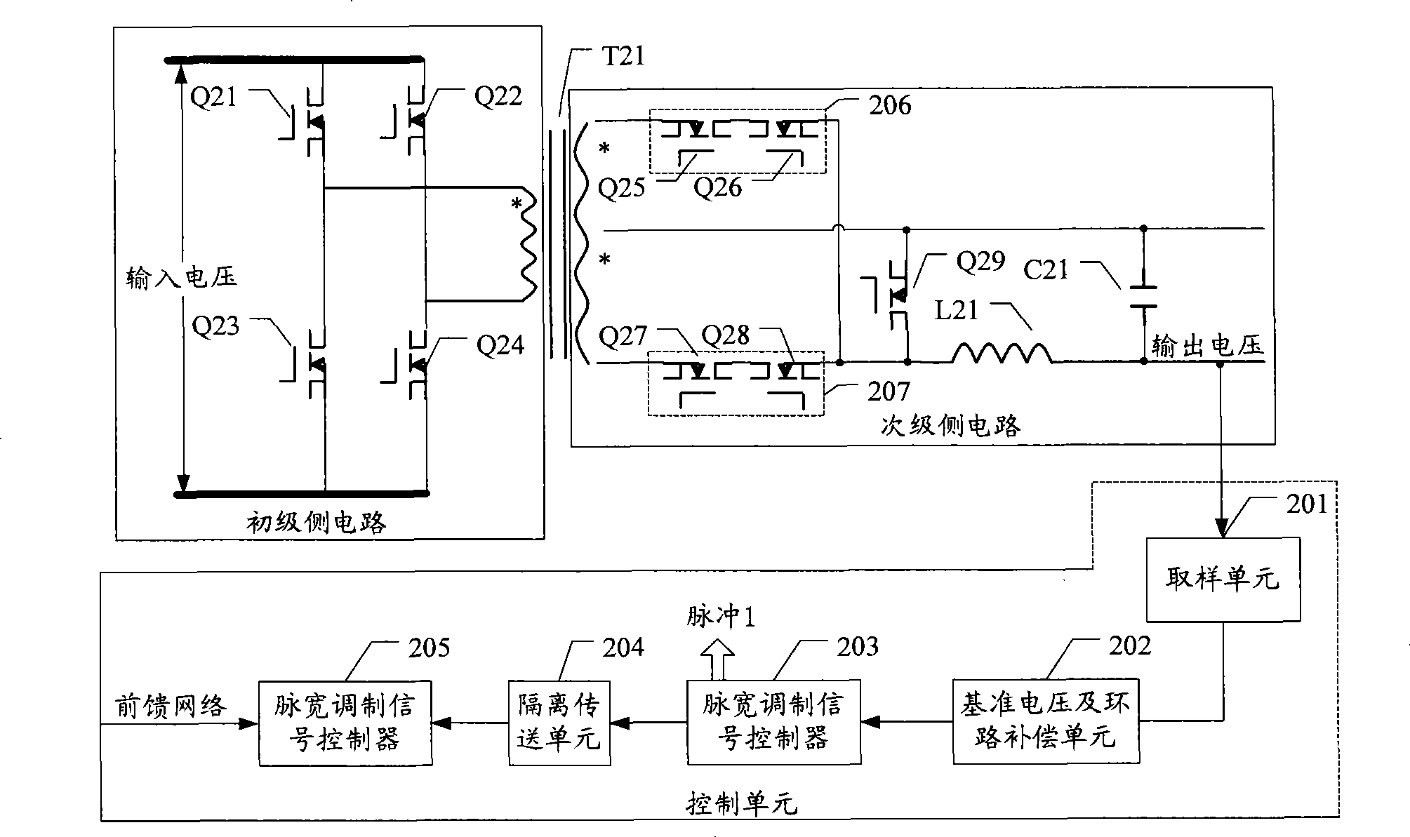
[0037] The invention provides a method for improving a DC conversion power supply device and the corresponding DC conversion power supply device. A circuit with a shaping function and a rectification function is coupled to the secondary winding of the transformer. The feedback adjustment signal directly adjusts the circuit to obtain the target DC voltage.

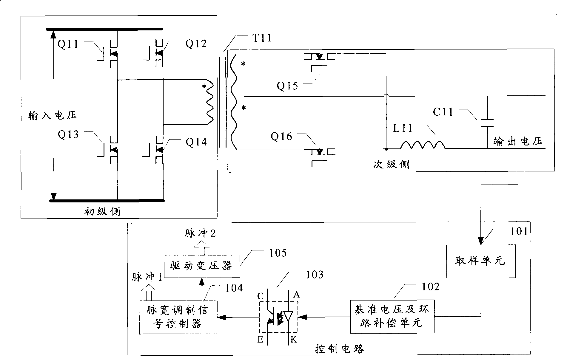
[0038] The embodiment of the DC conversion power supply device provided by the embodiment of the present invention generally includes: a transformer, a circuit on the primary side of the transformer, a circuit on the secondary side of the transformer, and a control unit.

[0039] The circuit coupled to the primary winding of the transformer is the primary side circuit of the transformer.

[0040] The circuit coupled to the secondary winding of the transformer is the secondary side circuit of the transformer. In the embodiment of the DC conversion power supply device provided in the embodiment of the present invention, it is...


PUM


Abstract

The invention discloses a DC converting power supply device. The device comprises a transformer, a transformer primary side circuit, a transformer secondary side circuit; the transformer secondary side circuit comprises a rectifying circuit with the function of reshaping and transformation which is used to transform the square wave voltage output by the transformer to the DC output voltage; and the device also comprises a control unit which controls the transformer secondary side circuit according to the DC output voltage, adjusts the DC output voltage and facilitates the DC output voltage tobe the stable target value. The invention also discloses a method for improving the DC converting power supply device. The method comprises that: the secondary winding is coupled with a rectifying circuit with the function of reshaping and transformation, the square voltage output by the transformer is transformed into the DC output voltage; the DC output voltage is detected, according to the DC output voltage, the DC output voltage is adjusted to become the stable target value. By the invention, the dynamic performances of the DC converting power supply can be improved.

Description

technical field [0001] The invention relates to the field of electronic technology, in particular to a DC conversion power supply device and a method for improving the DC conversion power supply device. Background technique [0002] The commonly used isolated DC-to-DC (DC-DC, direct current-direct current) high-frequency switching power supply is used as a DC conversion power supply, and the full-bridge isolation conversion topology is mostly used. Its circuit structure is as follows: figure 1 Shown: [0003] This circuit includes: primary side circuit, secondary side circuit, and control circuit. The circuit coupled to the primary winding of the isolation main transformer T11 as shown in the figure is called the primary side circuit; the circuit connected to the output voltage terminal of the isolation main transformer T11 is called It is called the secondary side circuit; the control circuit includes: sampling unit 101, reference voltage and loop compensation unit 102, fe...

Claims


Application Information

Patent Timeline
Patent Type & Authority Applications(China)
IPC IPC(8): H02M3/28H02M3/335H02M7/217
CPCY02B70/1475H02M3/33592Y02B70/10
Inventor 刘志华
Owner HUAWEI TECH CO LTD
Why Eureka
Try Eureka