Braking systems with cooling

A brake system and brake ring technology, applied in the direction of brake type, brake components, mechanical equipment, etc., can solve the problems of reduced space, easy to be interrupted, and reduced heat dissipation efficiency.

Inactive Publication Date: 2009-04-01
威廉·爱德华·芬纳
View PDF0 Cites 7 Cited by
  • Summary
  • Abstract
  • Description
  • Claims
  • Application Information

AI Technical Summary

Problems solved by technology

Furthermore, the worsening of the piston effect is exacerbated by the reduced space within the relevant wheel for convection of air to cool the brake discs
[0007] Therefore, the main inherent problem with drum and disc brake systems is that cooling by air convection alone is often not enough to prevent brake fade
And the design of the braking system itself makes it easy for the air flow that should be used to cool the surface to be interrupted, thereby reducing the cooling efficiency

Method used


Image

  • Braking systems with cooling
  • Braking systems with cooling
  • Braking systems with cooling

Examples


Embodiment Construction

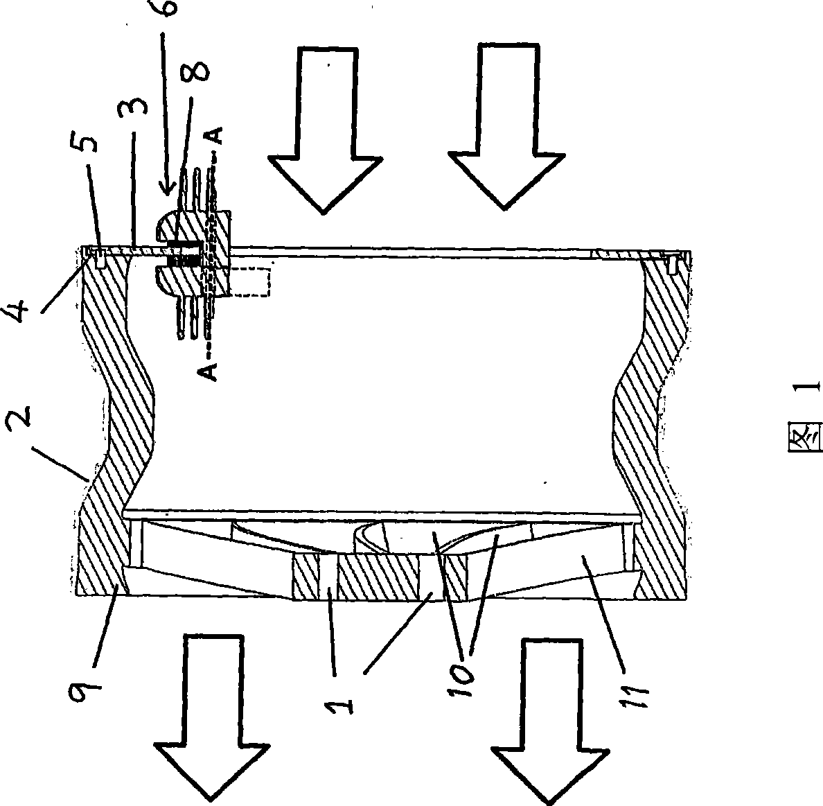
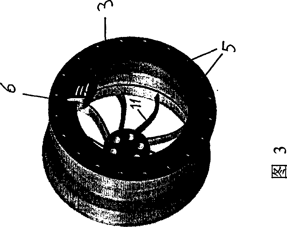
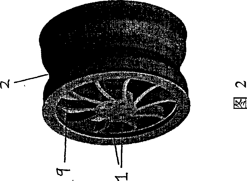
[0034] The car wheel shown in Figure 1 is the same as the existing wheels in that it includes a mounting hole 1 for positioning to the vehicle axle and a support 9, and the support 9 includes a wheel for fixing a pneumatic tire (not shown). Edge 2. It differs from existing motor vehicle wheels in that it comprises an annular brake ring 3 which is positioned in an annular recess 4 of the wheel rim 2 by countersunk screws 5 . The support member 9 extends from the center of the wheel to the rim 2 and is provided with a plurality of openings 10 .

[0035] The braking force applied to the brake ring 3 is applied to the brake ring 3 through the brake caliper 6 connected to the vehicle suspension. The braking force can be pushed to the brake ring 3 through a hydraulic brake hose (not shown) through a hydraulic brake hose (not shown). Moving washer 8, and make the latter friction fit with brake ring 3.

[0036] In use, the air flows over the brake caliper 6 and over the brake ring 3...


PUM


Abstract

A braking system comprises an axle (23), a support element (22) mounted on the axle, a brake ring (3) connected to the periphery of the support element (22) and a brake calliper (21) for applying a braking force to the brake ring (3). The brake ring (3) is connected to the support element (22) in such a manner that a conductive heat flow path is provided for conducting heat from the brake ring (3) into the support element (22). There is also an airflow path passing through the support element (22) and through the region in which the brake calliper (21) is situated for transferring heat by convection from the brake ring (3) and the brake calliper (21).

Description

technical field [0001] The invention relates to a braking system, in particular to a braking system for motor vehicle wheels. Background technique [0002] Motor vehicle wheel braking systems usually use a braking system that includes a friction surface with a high friction coefficient to decelerate the wheel, thereby converting kinetic energy into heat energy to achieve braking. The problem is that if the generated heat is not dissipated, the system's braking The effect will get worse and worse, and eventually the brakes will fail due to so-called brake fade. [0003] Drum brakes are especially prone to brake fade because the hub friction generates more heat than the surrounding air can dissipate the heat by convection. [0004] Disc brakes are generally more efficient than drum brakes because more pressure is applied through the caliper to squeeze the brake pads against the brake pads attached to the hub compared to the pressure on the inner surface of the drum in drum br...

Claims


Application Information

Patent Timeline
IPC IPC(8): F16D65/847
CPCF16D65/847F16D2065/1372F16D65/853
Inventor 威廉·爱德华·芬纳
Owner 威廉·爱德华·芬纳
Why Eureka
Try Eureka