Double-side exposal device

An exposure device and two-sided technology, which are applied to photolithographic process exposure devices, microlithography exposure equipment, optics, etc., can solve the problems of difficulty in adjustment and control, large-scale devices, and high costs, shortening the replacement operation time, and reducing the size of the device. Optimizing, setting the effect of small space

Inactive Publication Date: 2009-04-08
ADTEC ENG
View PDF0 Cites 4 Cited by
  • Summary
  • Abstract
  • Description
  • Claims
  • Application Information

AI Technical Summary

Problems solved by technology

[0003] However, in the conventional device, since there are two light source devices, the exposure conditions on the front and back are sometimes changed depending on the individual differences of each device and lamp, and there are adjustments and controls for performing the same exposure on the front and back Difficult, very troublesome problem
[0004] In addition, since two light source devices are installed in one exposure device, there are problems of high cost and large size of the device

Method used


Image

  • Double-side exposal device

Examples


Embodiment Construction

[0012] Embodiments of the present invention will be described below with reference to the drawings.

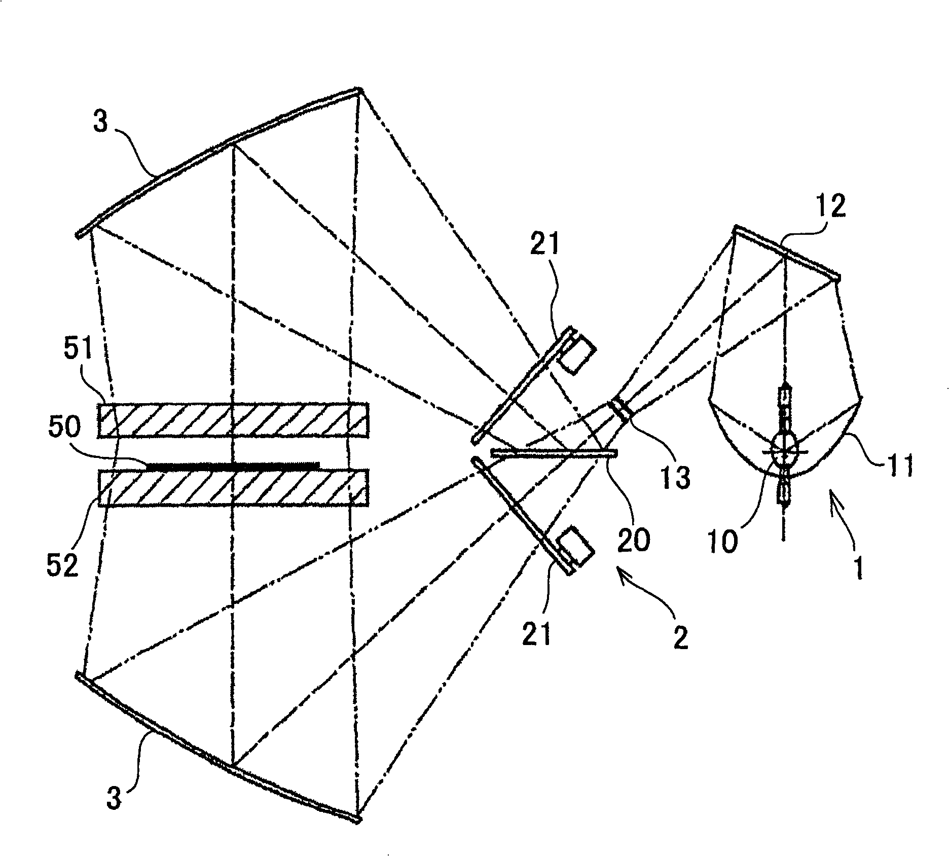
[0013] exist figure 1 In the configuration, the substrate 50 to be exposed is placed on the photomask 52 , and the patterns drawn on the photomask 51 and the photomask 52 located above the substrate 50 are exposed on the front and rear surfaces of the substrate 50 .

[0014] The light source device of this double-sided exposure apparatus includes: a single light source unit 1; a spectroscopic unit 2; and collimator mirrors 3, 3 provided on the front side and the back side of the substrate 50, respectively.

[0015] The light source unit 1 has a light source lamp 10, an elliptical mirror 11, a reflector 12, and a fly-eye lens 13. The light emitted from the light source lamp 10 is converged by the elliptical mirror 11 and returned by the reflector 12, and then passes through the fly-eye lens ( fly eye lens) 13 partial focus.

[0016] The spectroscopic unit 2 has a spectroscopi...


PUM


Abstract

The invention provides a two-sided exposure device, which can expose the surface and back face of the substrate under identical exposure condition without any bothersome modulation and control. The lights emitted from a light source lamp (10) converge at an oval mirror (11) convergence, turn back through a reflector (12), partly focus at a fly's-eye lens (13); and then the light is divided into a reflected light and a transmitted light through a spectroscope (20), pass through a light source light shutter (21) to control the luminous quantity, further it is reflected by a collimating mirror (3) as a parallel light, and then permeates a photo mask (51) and a light mask (52) to irradiate on the surface side and back face side of the substrate (50).

Description

technical field [0001] The present invention relates to a double-side exposure device for exposing both surfaces of a printed wiring board. Background technique [0002] In a parallel-light double-side simultaneous exposure apparatus for simultaneously exposing the front and back of a printed circuit board, conventionally, two lamps for the front and back are provided as light sources in order to expose the front and back separately. [0003] However, in the conventional device, since there are two light source devices, the exposure conditions on the front and back are sometimes changed depending on the individual differences of each device and lamp, and there are adjustments and controls for performing the same exposure on the front and back Difficult, very troublesome questions. [0004] In addition, since two light source devices need to be mounted on one exposure device, there are problems of high cost and large size of the device. Contents of the invention [0005] ...

Claims


Application Information

Patent Timeline
Patent Type & Authority Applications(China)
IPC IPC(8): G03F7/20G02B27/00H05K3/00H05K3/06
CPCG03F7/2022G03F7/70558
Inventor 浅见正利
Owner ADTEC ENG
Why Eureka
Try Eureka