Locking method for self-spinning lock and computer system

A computer system and spin lock technology, applied in the computer field, can solve problems such as delaying the debugging cycle, failure to detect, waste of manpower and material resources, etc., and achieve the effect of shortening the debugging cycle

Inactive Publication Date: 2009-04-08
HUAWEI DIGITAL TECH (CHENGDU) CO LTD
View PDF0 Cites 19 Cited by
  • Summary
  • Abstract
  • Description
  • Claims
  • Application Information

AI Technical Summary

Problems solved by technology

However, it is impossible to know which part of the software code is locked and has not been released, resulting in the failure of the current code to acquire the lock, so the error location cannot be detected, and the staff needs to write codes for debugging and use various laboratory methods for positioning, which not only wastes manpower and material resources, but also often leads to failure Delay in debugging cycle

Method used


Image

  • Locking method for self-spinning lock and computer system
  • Locking method for self-spinning lock and computer system
  • Locking method for self-spinning lock and computer system

Examples


Embodiment Construction

[0022] The following will clearly and completely describe the technical solutions in the embodiments of the present invention with reference to the accompanying drawings in the embodiments of the present invention. Obviously, the described embodiments are only some, not all, embodiments of the present invention. Based on the embodiments of the present invention, all other embodiments obtained by persons of ordinary skill in the art without making creative efforts belong to the protection scope of the present invention.

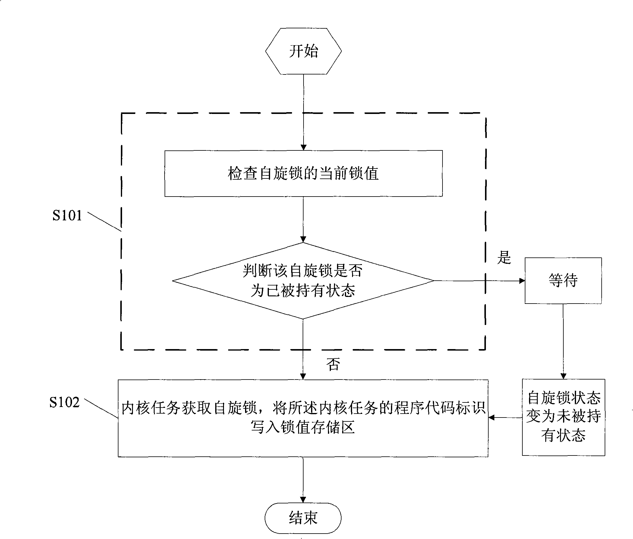
[0023] See figure 1 as shown, figure 1 It is a flow chart of the first embodiment of the locking method of the spin lock of the present invention. Such as figure 1 As shown, the method specifically includes:

[0024] Step S101, check the current lock value of the spin lock, and judge whether the spin lock is held. The state of the spin lock is judged according to the value of the lock value. In this embodiment, the lock value of the spin lock is stored in ...


PUM


Abstract

The invention relates to a locking method of a spin lock, comprising the following steps: the spin lock is detected to be in an un-held state; an inner core task acquires the spin lock; a procedure code mark in the inner core task is written into a lock value storage area; the lock value storage areas is used for storing the lock values of the spin lock. Correspondingly, the embodiment of the invention also discloses a locking device and a computer system of the spin lock. By the procedure code mark written into the inner core task in the storage area which represents the lock value of the spin lock, the embodiment can quickly locate the position of an error according to the information in the storage area when the spin lock is dead locked, and shortens the adjustment cycle greatly while occupying a relatively small space of the system.

Description

technical field [0001] The present invention relates to the computer field, in particular to a spin lock locking method and device and a computer system in the computer field. Background technique [0002] Multi-core processors are widely used in high-end embedded systems. Multi-core processors integrate multiple processor cores in one processor chip. Each processor core can run programs independently, making the programs think that they are running in an independent on the processor. Unlike multiple computers, all processor cores of a multicore processor can use the same bus to access memory, so they can share the same piece of memory; they may also share the same set of on-chip devices. In embedded systems, not only operating systems and drivers, but also applications often use resources such as shared memory and hardware registers. However, multi-core processors often need to use shared resources exclusively, such as a piece of shared memory. If two processor cores writ...

Claims


Application Information

Patent Timeline
Patent Type & Authority Applications(China)
IPC IPC(8): G06F9/46
Inventor 李珅
Owner HUAWEI DIGITAL TECH (CHENGDU) CO LTD
Why Eureka
Try Eureka