Underwater sound communication processing platform

A processing platform and underwater acoustic communication technology, applied to electrical components, transmission systems, etc., can solve problems such as unsuitable for real-time, high-speed underwater acoustic communication, backward modulation and demodulation technology of underwater acoustic communication, and processing capacity that cannot meet the needs, etc., to achieve Simplified program design, convenient interconnection, and fast processing effects

Inactive Publication Date: 2009-04-08
HARBIN ENG UNIV
View PDF0 Cites 13 Cited by
  • Summary
  • Abstract
  • Description
  • Claims
  • Application Information

AI Technical Summary

Problems solved by technology

[0003] Although the underwater acoustic communication technology has made rapid progress in recent years, there are still several obvious deficiencies in the current underwater acoustic communication system: First, there are not many domestic and foreign systems of the current underwater acoustic communication technology, and The underwater acoustic communication modulation and demodulation technology used is relatively backward, let alone the practical application of underwater acoustic communication technology; secondly, the current underwater acoustic communication system mainly completes simple underwater communication tasks. Low, the use of low-speed serial communication is not suitable for real-time, high-speed underwater acoustic communication; again, in view of the large amount of calculation, strong real-time, high speed and other requirements faced by the current new underwater acoustic communication technology, the current underwater acoustic communication system processing Most of the capacity is far from meeting the demand

Method used


Image

  • Underwater sound communication processing platform
  • Underwater sound communication processing platform
  • Underwater sound communication processing platform

Examples


Embodiment Construction

[0026] The present invention is described in more detail below in conjunction with accompanying drawing example:

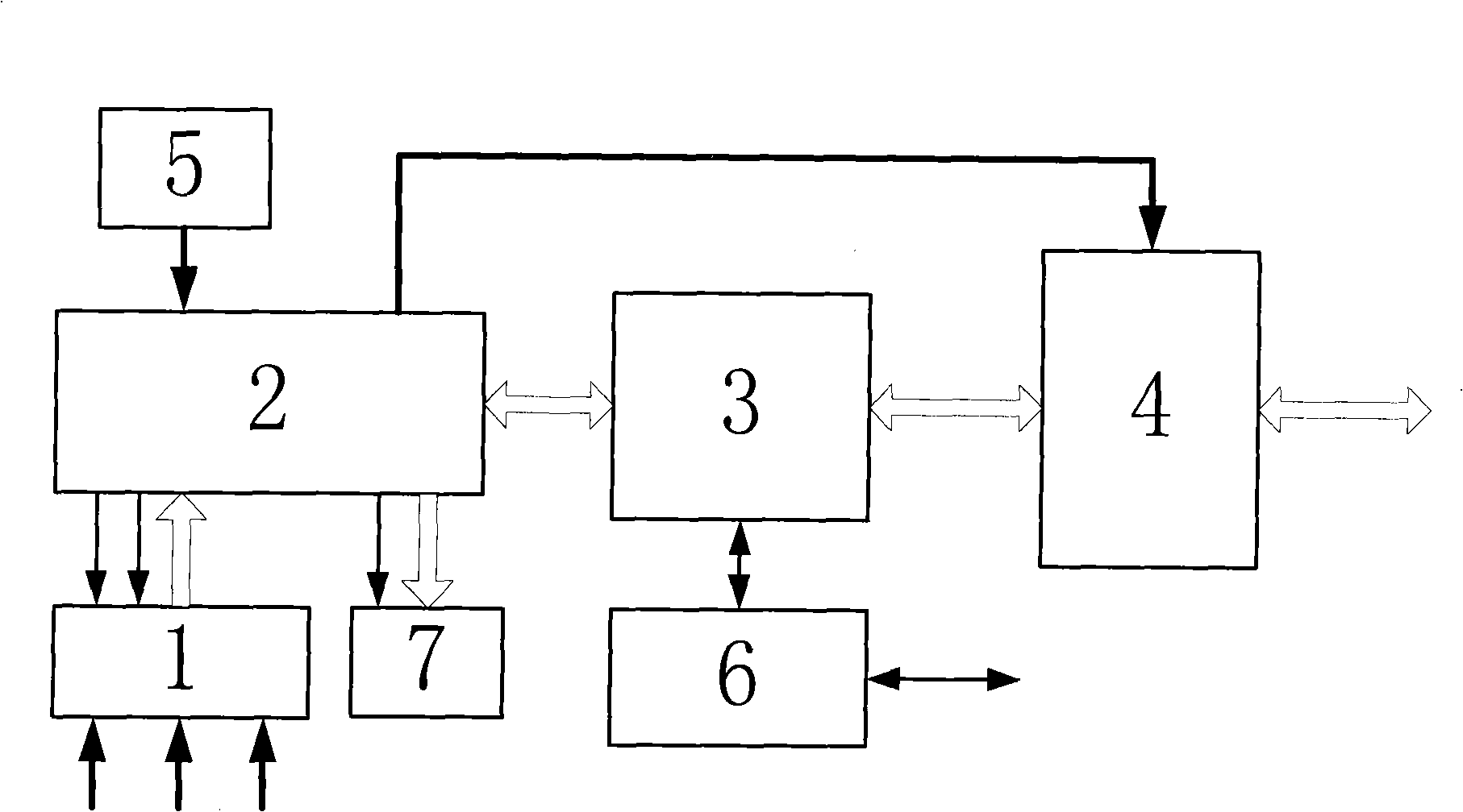
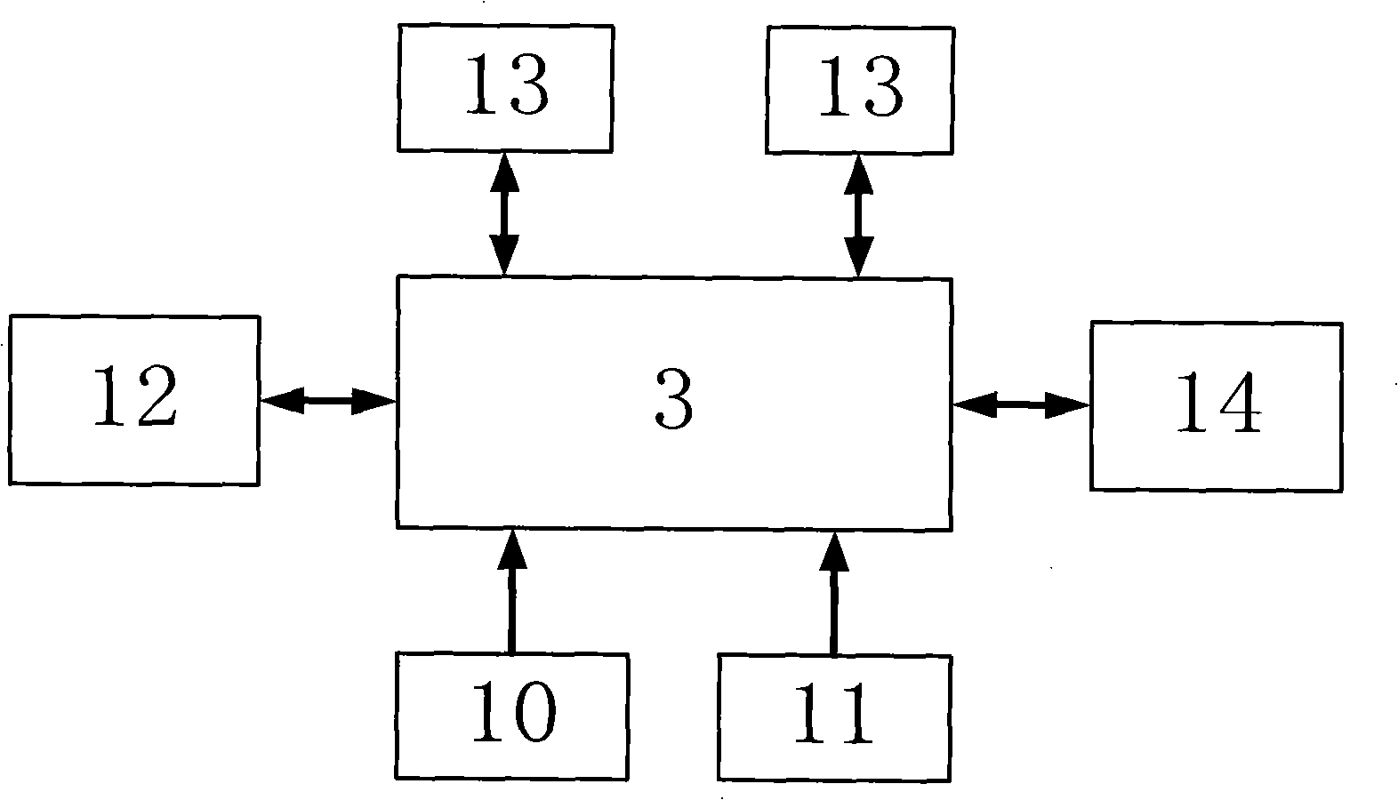
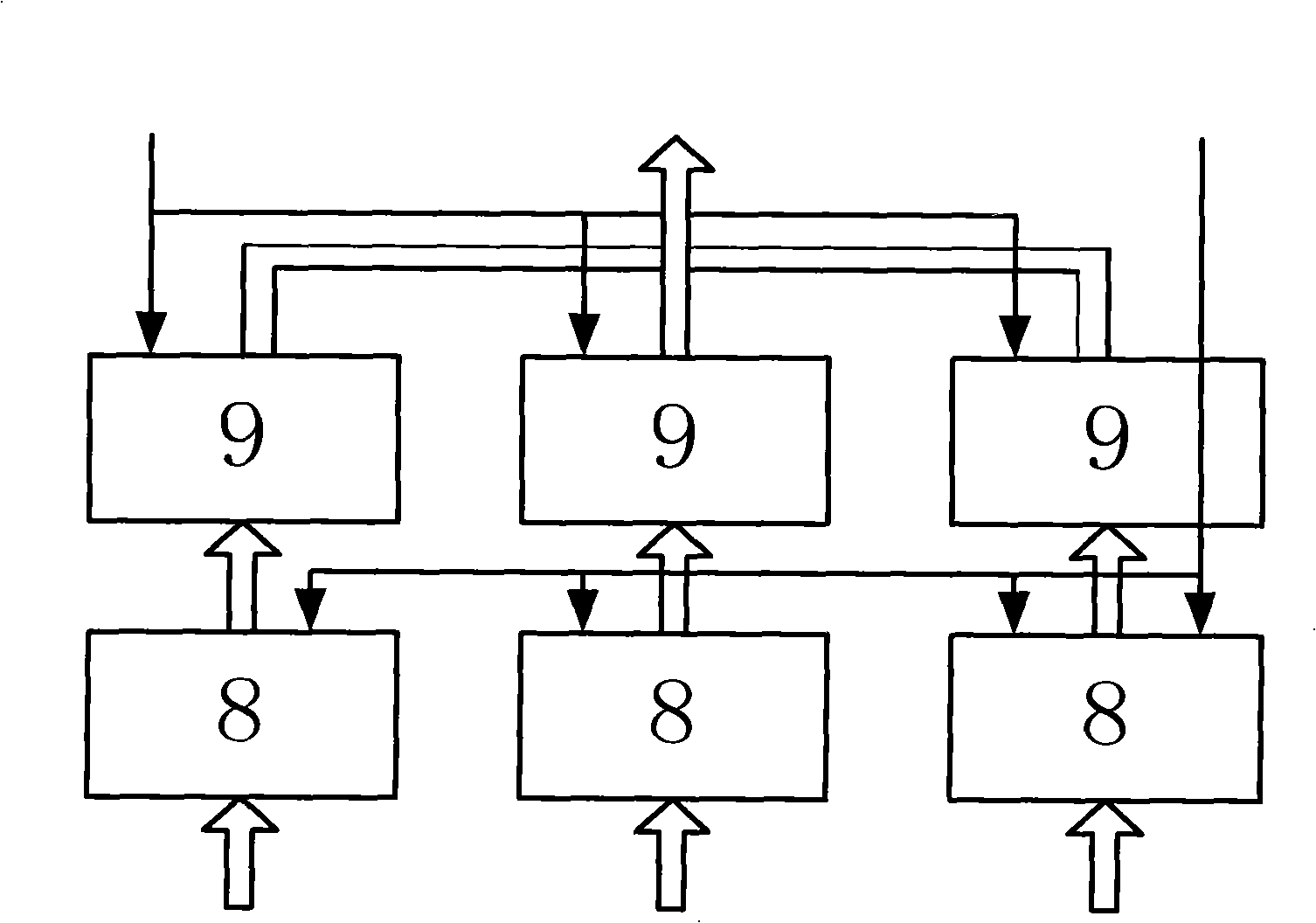
[0027] combine figure 1, the field programmable logic device FPGA2 is the connection node of each functional module circuit of the processing board, and mainly completes the logic control of each functional module. It has abundant on-chip resources and I / O pins, and plays the role of interconnecting circuits and storage control. . The front-end analog-to-digital conversion circuit 1 of the processing board is connected with the general-purpose I / O port of the FPGA2 through a set of data buses through a parallel interface, and mainly completes digital quantization of analog signals. The high-precision, low-noise D / A8 digital-to-analog conversion chip at the front end of the processing board is connected to the general-purpose I / O port of FPGA2 through parallel data lines, and mainly completes the conversion of digital signals on the processing board into analog si...


PUM


Abstract

The invention provides an underwater acoustic communication processing platform. The platform comprises an FPGA; an analog / digital conversion circuit on a front end of a processing board is connected with a general purpose I / O interface of the FPGA, and a digital / analog (D / A) conversion chip on the front end of the processing board is connected with the general purpose I / O interface of the FPGA; a DSP is connected with the FPGA by a data bus with EMIFA interfaces inside and outside of a chip; a chip selector, a read-write control line and a partial address line of the EMIFA interface are connected with the general purpose I / O interface of the FPGA; two DDR2 external dynamic memories of 128M are connected with a DDR2 dedicated control interface on a DSP chip by the data bus; the data bus and the address line of a network transmission module are interconnected with the EMIFA interface of the DSP; the chip selector and a read-write control signal are connected with an general purpose I / O pin of the FPGA; the DSP controls the network transmission by the FPGA; and a serial communication circuit is interconnected with an MCBSP interface of the DSP. The platform greatly improves the communication ability, has small size and smart and diverse application, and can play a role in underwater target detection and navigation, underwater voice communication, ultrahigh speed real-time underwater acoustic communication and the like.

Description

(1) Technical field [0001] The invention relates to a novel processing platform structure for real-time underwater acoustic communication. (2) Background technology [0002] Underwater acoustic communication is the transmission of data or control information using underwater acoustic channels. The history of underwater acoustic communication can be traced back to 1914. The successful development of the underwater acoustic telegraph system can be regarded as the prototype of underwater wireless communication. The truly reliable underwater acoustic analog communication system appeared after World War II. The system uses modulation technology for communication between submarines. In 1945, the United States developed the first well-functioning underwater telephone system for communication between submarines. However, the structural performance of the underwater acoustic communication system in this period was low, the communication technology was not perfect, and the operating...

Claims


Application Information

Patent Timeline
Patent Type & Authority Applications(China)
IPC IPC(8): H04B13/02
Inventor 乔钢蒋超华孙宗鑫徐小卡周峰马雪飞
Owner HARBIN ENG UNIV
Why Eureka
Try Eureka