Opposed piston engine

An opposed-piston, engine technology, applied in engine components, machines/engines, engine cooling, etc., to solve problems such as difficulty in providing effective sealing of cylinders and pistons, inability to maintain tight tolerances, and inability to prevent piston crown expansion.

Inactive Publication Date: 2009-04-08
ACHATES POWERS INC
View PDF2 Cites 10 Cited by
  • Summary
  • Abstract
  • Description
  • Claims
  • Application Information

AI Technical Summary

Problems solved by technology

The cooling system of the Bird engine provides liquid coolant within the engine block through the cylinder sleeves, but the system does not alleviate the uneven twisting of the cylinders, nor does it prevent the expansion of the piston crowns
As a result, tight tolerances between cylinder and pisto...

Method used


Image

  • Opposed piston engine
  • Opposed piston engine
  • Opposed piston engine

Examples


Embodiment Construction

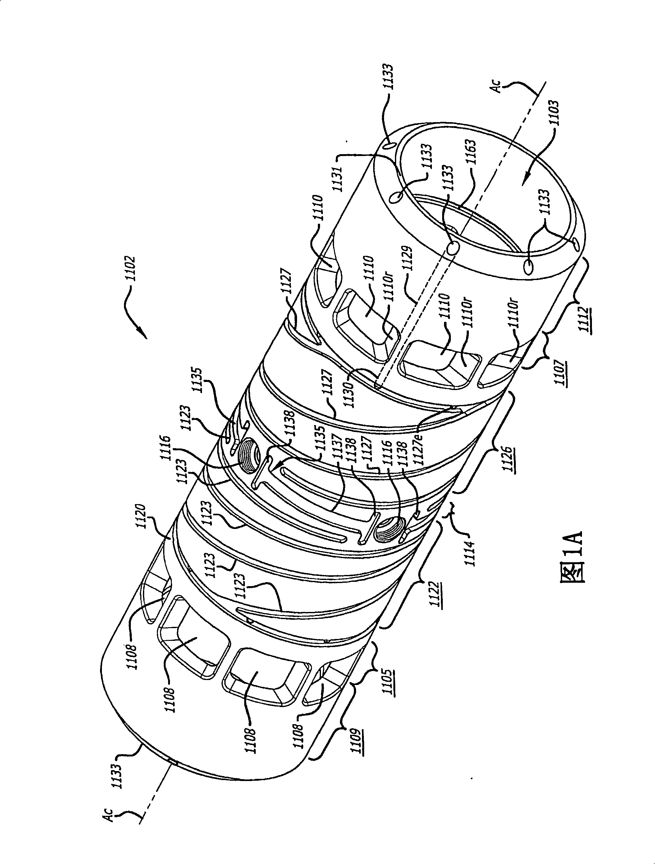
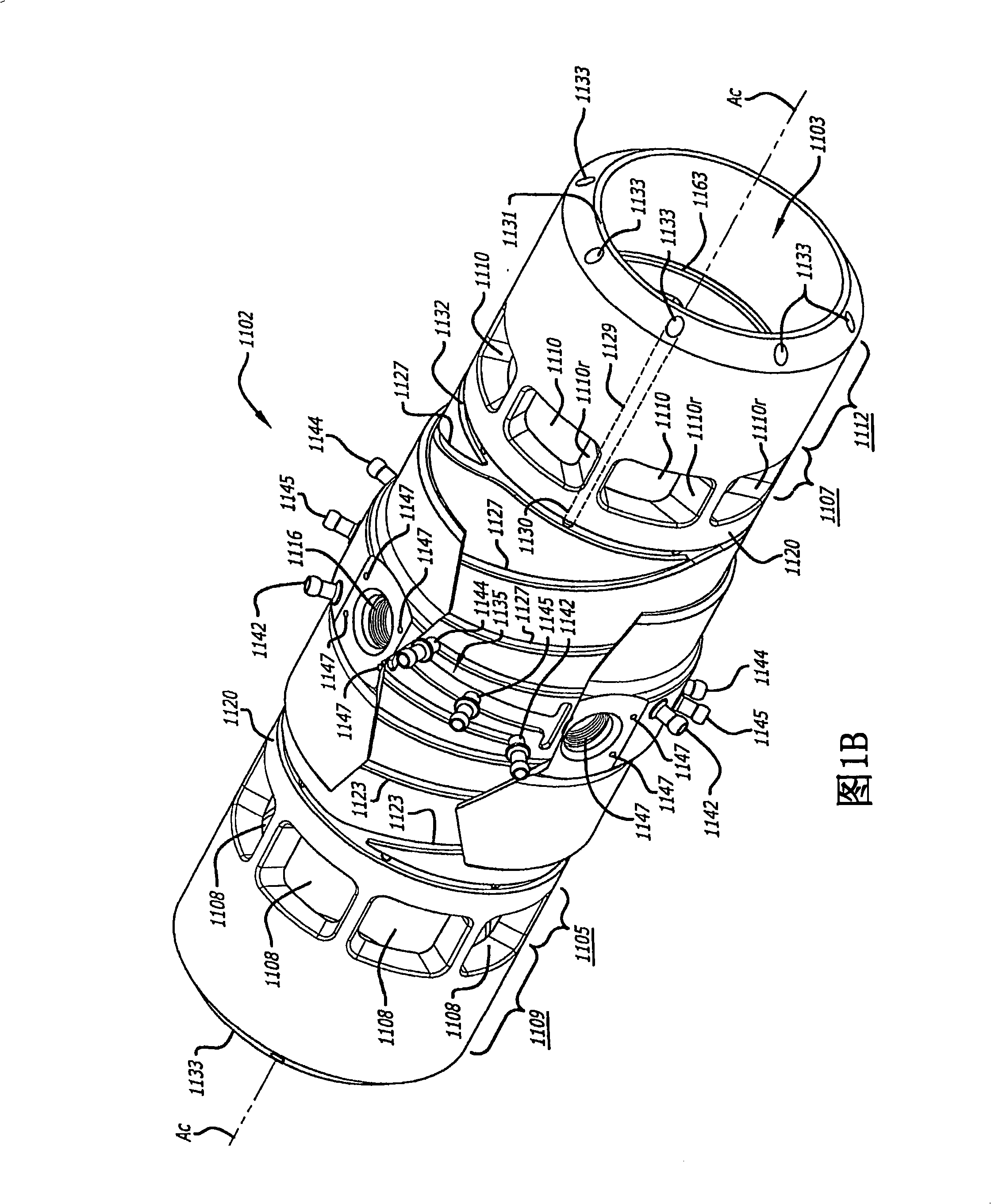
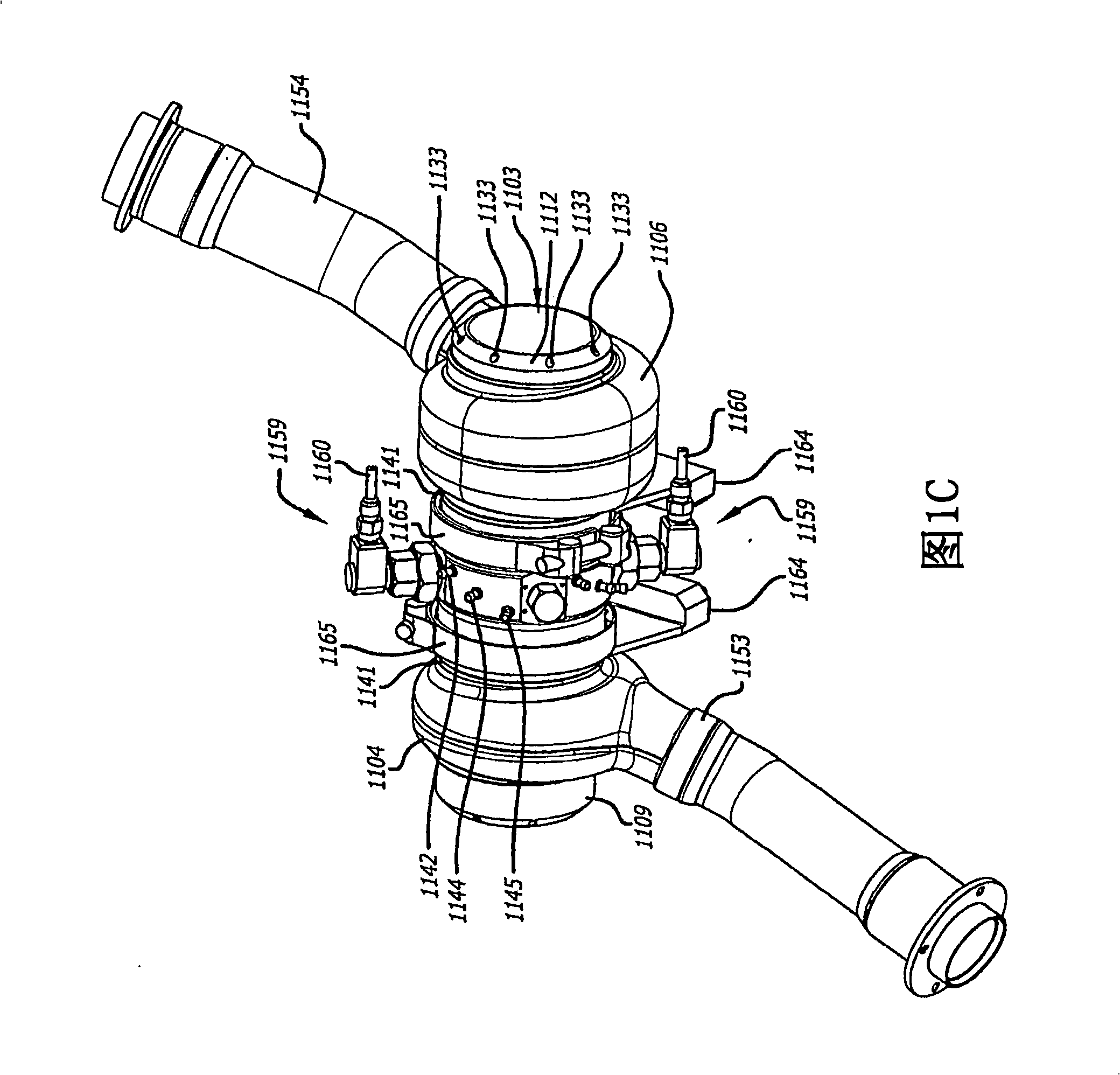
[0021] 1A-1D illustrate a cylinder 1100 that may be used in an opposed-piston internal combustion engine. The cylinder 1100 has four parts: a cylinder liner 1102 formed as an open cylindrical tube with a cylindrical bore 1103 , an exhaust manifold 1104 , an intake manifold 1106 and a cylinder sleeve 1140 . Cylinder 1100 is preferably made of aluminum such as high temperature aluminum alloy and may be cast as a single piece or assembled by securing manifolds 1104 and 1106 to cylinder sleeve 1140 and subsequently securing the subassembly to the outer surface of cylinder liner 1102 form. Longitudinal axis A of cylinder liner 1102 c Also the longitudinal axis of cylinder 1100 .

[0022]As best shown in FIG. 1A , the cylinder liner 1102 has an exhaust port 1105 consisting of a series of circumferentially spaced openings 1108 proximate an exhaust end 1109 of the cylinder liner 1102 . The cylinder liner 1102 also has an intake port 1107 consisting of a series of circumferentially ...


PUM


Abstract

A two-cycle, opposed piston engine with side-mounted crankshafts and cylinders isolated from mechanical stresses of the engine includes tailored cooling of cylinders and symmetrical cooling of the interior surfaces of piston crowns. Each opposed piston includes a compliant member that permits movement of an axially-centered rod mounted in the piston in order to maintain axial alignment with the bore of a cylinder in which the piston is disposed during engine operation. A single wristpin is disposed externally of the piston to connect the piston with connecting rods that run between the piston and the crankshafts.

Description

[0001] related application [0001] This application claims priority under 35 U.S.C. §119 as a continuation-in-part of PCT Patent Application PCT / US2005 / 020553, filed June 10, 2005, entitled "Improved Two-Stroke Opposed-Piston Internal Combustion Engine," and claims pursuant to 35 U.S.C. §120 claims priority as a continuation-in-part of U.S. Patent Application Serial No. 10 / 865,707, Two-Stroke Opposed-Piston Internal Combustion Engine, filed June 10, 2004, the disclosure of which is hereby incorporated by reference in its entirety. Background technique [0002] The present invention relates to internal combustion engines. More specifically, the present invention relates to cooling two-stroke opposed-piston engines adapted to the specific requirements of each cylinder and piston, wherein a single piston pin connects each piston to an associated connecting rod, and compliant piston connectors maintain alignment between each piston and associated cylinder. straight. [0003] Th...

Claims


Application Information

Patent Timeline
IPC IPC(8): F02B75/28F02B75/06F01P3/02F01P3/10F01P3/00F01P3/06F01P3/08F02B75/32F02F1/18F16H1/22
CPCF02B75/065F01P3/06F16H1/22F01P2003/021F02B75/282F02B75/28F01P2003/005F01P3/10F01P2003/028F02F1/186F01P2003/006F02B75/32F01P2003/027F01P3/02F02B75/06
Inventor J·U·莱姆基R·J·霍夫曼M·H·沃尔P·R·李
Owner ACHATES POWERS INC
Why Eureka
Try Eureka