Systems with reciprocating piston engines

A technology of reciprocating piston and engine, applied in the direction of internal combustion piston engine, engine starting, engine components, etc., can solve problems such as trouble, limit the maximum electric power of motor converter, permanent magnet detachment, etc., to prevent adverse effects and reduce long-term demagnetization. Effect

Active Publication Date: 2018-10-09
HVD
View PDF5 Cites 0 Cited by
  • Summary
  • Abstract
  • Description
  • Claims
  • Application Information

AI Technical Summary

Problems solved by technology

Since the crankshaft balance weights, for their general purpose, only extend in the opposite range to the adjacent connecting rod bearings (which range is generally considered to be less than 120° and thus encompass less than one-third of the circumference of rotation), the balance weights The heavy permanent magnets can only

Method used


Image

  • Systems with reciprocating piston engines
  • Systems with reciprocating piston engines
  • Systems with reciprocating piston engines

Examples


Embodiment Construction

[0102] Since these figures partly show the same exemplary embodiment from different perspectives and in different levels of detail, and these exemplary embodiments only partly differ in certain features, the following description of these figures will partly A repeated explanation of reference signs and features already mentioned above will not be provided, and in part only the differences between the various exemplary embodiments will be discussed.

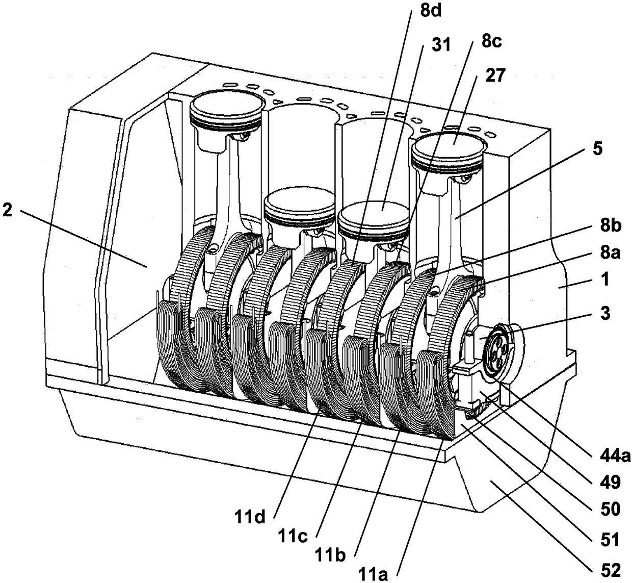
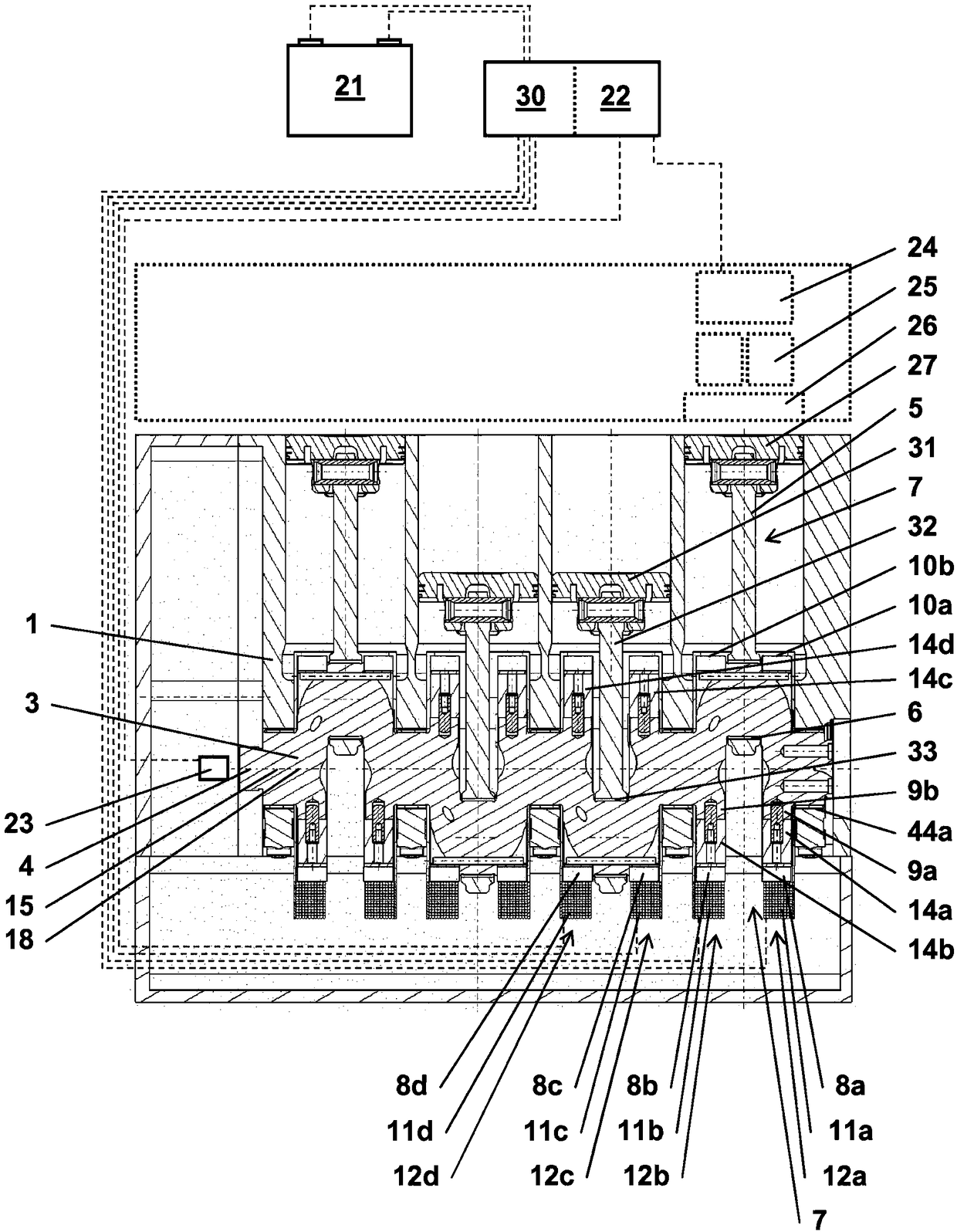
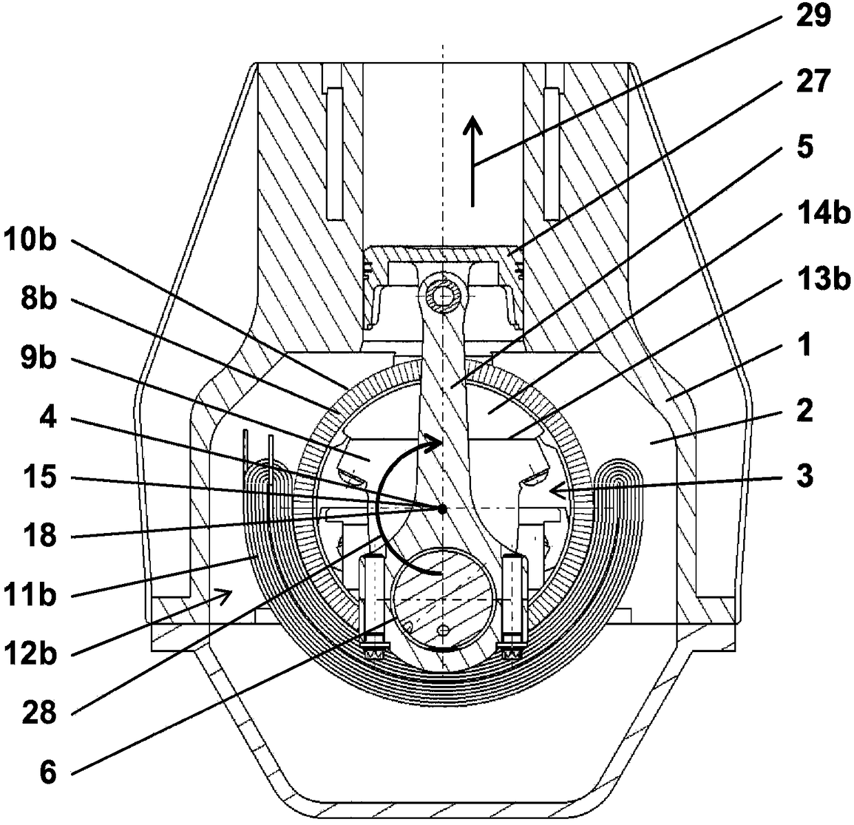
[0103] Figure 1A to Figure 1J The first exemplary embodiment of the reciprocating piston engine according to the invention is shown from different perspectives and with different levels of detail. The figures will be discussed collectively below.

[0104] The reciprocating piston engine of the first exemplary embodiment is a four-cylinder in-line engine operating according to the Otto cycle engine principle, as Figure 1A with Figure 1B shown. This reciprocating piston engine basically consists of a cylinder block 1 , a cran...


PUM


Abstract

A reciprocating piston engine is disclosed having a first inner magnetic field unit, arranged on a first crank web of a crankshaft, and a stationary first outer magnetic field unit, wherein the first inner magnetic field unit and the first outer magnetic field unit together form a first electromagnetic converter, in particular an electric motor or an electric generator. The first crank web has a first compensating weight on a side that is opposite a first connecting rod bearing and that faces radially outwards in relation to a crankshaft axis, wherein the first compensating weight is made of a non-magnetizable material. The first inner magnetic field unit is arranged on a side of the first compensating weight that faces outwards in relation to the crankshaft axis. The invention also relates to a system comprising the reciprocating piston engine, an energy store, an electric control unit and a crankshaft sensor.

Description

technical field [0001] The invention relates to a reciprocating piston engine with an electromechanical converter operable as a generator and / or as an electric motor, and to a system with a reciprocating piston engine. Background technique [0002] EP 1 223 316 B1 discloses a reciprocating piston engine, in the crankcase of which is arranged an electromechanical converter which has the function of an electric motor and / or a generator. A magnetic field generating element in the form of a permanent magnet is arranged on a crankshaft held rotatably in the crankcase by a bearing cap attached to the cylinder block. The permanent magnet is fixedly inserted by interference fit in the recess of the balance weight of the crankshaft and serves as an additional balance weight. The coil is held stationary in the crankcase, on the bearing cap. During the rotation of the crankshaft, the permanent magnet rotates relative to the stationary coil, whereby a voltage is induced in the coil du...

Claims


Application Information

Patent Timeline
IPC IPC(8): F02B63/04H02K7/18B60K6/485B60W20/00
CPCB60K6/24B60K6/485B60Y2300/437F02B63/04F02B63/042F02D13/0246H02K7/1815Y02T10/12Y02T10/62Y10S903/905Y10S903/906B60K6/26B60Y2200/92B60Y2400/43B60Y2400/60F02F1/00F02F7/00F02N11/04F16C3/06H02K7/1884
Inventor A·舒藤巴赫·冯K-H·格拉布赫尔
Owner HVD
Why Eureka
Try Eureka