
A variable stroke free piston engine

A piston engine and engine technology, applied in the direction of free piston engine, internal combustion piston engine, combustion engine, etc., can solve the problems of increased engine weight and cost, low controllability, high difficulty in design and production, and achieve good fuel economy and Power, variable compression ratio, and high utilization

Active Publication Date: 2019-12-27
江苏铱莱德驱动系统有限公司
View PDF6 Cites 0 Cited by
  • Summary
  • Abstract
  • Description
  • Claims
  • Application Information

AI Technical Summary

Problems solved by technology

[0005] At present, there are three main schemes for realizing variable stroke technology: the first one is to configure two-stroke cylinders on the engine, and use two-stroke cylinders and four-stroke cylinders to work separately according to actual needs, that is, multi-cylinder cooperation mode, the engine The utilization rate is low, which increases the weight and cost of the engine; the second is to use a set of gas distribution system to meet the gas distribution of two-stroke and four-stroke at the same time, and the camshaft is provided with two-stroke gas distribution lines and four-stroke gas distribution lines. The profile line and the transition profile line for switching use hydraulic or mechanical drive to change the position of the variable cam to complete the switching of the gas distribution. The design and production are difficult, the controllability is low, and good fuel economy cannot be obtained; The third is to change the structure of the engine block, combine the intake and exhaust valve distribution of the four-stroke engine with the scavenging and ventilation of the two-stroke engine, and use the combination of different air passage closures to complete the work of each stroke , the engine utilization rate of this scheme is high, but the variable compression ratio cannot be realized, and the utilization of different fuels cannot be realized, which has limitations in fuel adaptability and fuel economy

Method used


Image

  • A variable stroke free piston engine
  • A variable stroke free piston engine
  • A variable stroke free piston engine

Examples


Embodiment 1

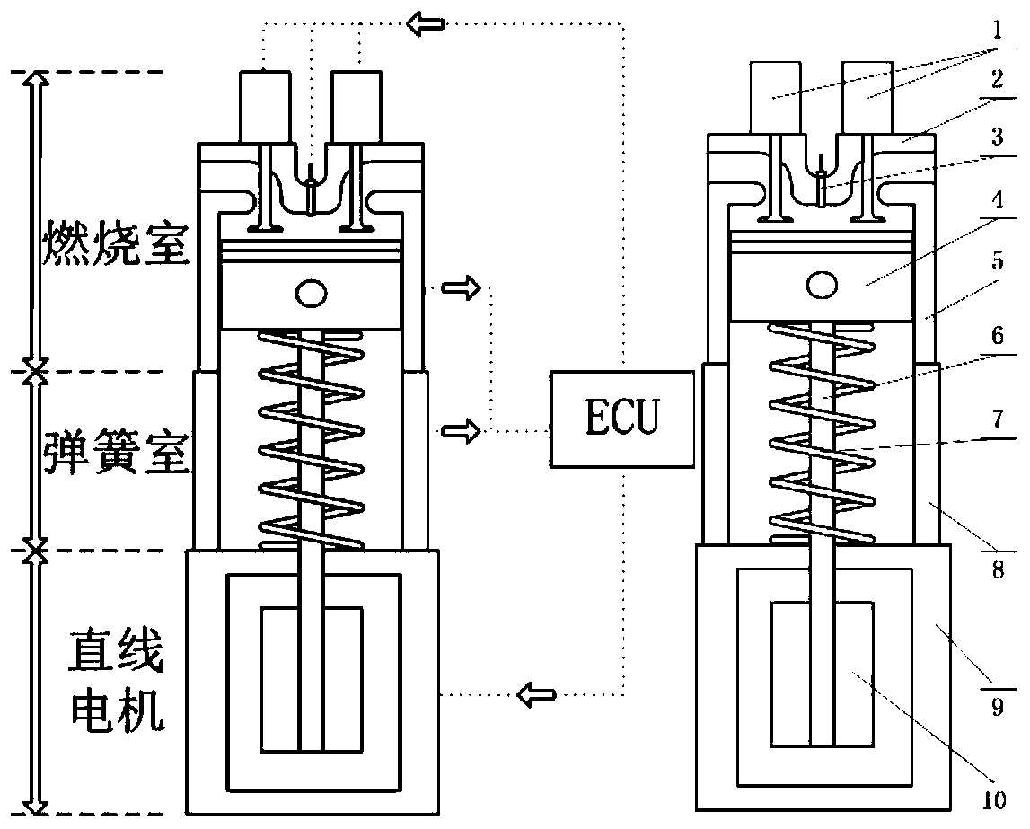
[0029] to combine figure 1 , a variable-stroke free-piston engine of the present invention includes four parts: a combustion chamber part, a spring chamber part, a permanent magnet linear motor part and an electronic control unit part.

[0030] in:

[0031] The combustion chamber part includes a variable valve mechanism 1, an engine cylinder head 2, an engine block 5, a piston 4 and a spark plug 3, wherein the variable valve mechanism 1 changes the valve lift, valve opening time, The valve opening duration realizes the fully flexible control of engine air distribution; the upper and lower dead centers of the piston 4 are variable, and the compression ratio is variable;

[0032] The spring chamber part includes a spring 7 and a bracket 8, wherein the spring 7 is fixed between the engine piston 4 and the linear motor. When the piston 4 goes down, the spring 7 is compressed to limit the displacement of the piston 4 and store energy. When the piston 4 goes up, the spring 7 provid...


PUM


Abstract

The invention discloses a stroke-variable free piston engine. The engine comprises a combustion chamber part, a spring chamber part, a permanent magnet linear motor part and an electronic control unitpart. A cam-free variable valve timing manner is adopted, and fully-flexible control over an inlet valve and an exhaust valve is achieved by electromagnetically driving a valve timing mechanism; an electronic control unit controls displacement of a piston by adjusting the powering-on current magnitude and direction of a permanent magnet linear motor coil, and the upper stop point, the lower stoppoint and the compression ratio of the piston are variable; and real-time control over the valve starting moment, the valve lift curve and the valve timing duration time is achieved by changing a control signal of the cam-free variable valve timing mechanism. The stroke-variable free piston engine is simple in structure and high in efficiency, fully-flexible control over various execution mechanisms of the engine is achieved, and the energy saving and environment protection performance of the engine is improved.

Description

technical field [0001] The invention relates to the technical field of vehicle engines, in particular to a variable stroke free piston engine. Background technique [0002] Reciprocating cycle engines are divided into two-stroke engines and four-stroke engines according to the number of strokes in one working cycle. A working cycle of a two-stroke internal combustion engine is divided into two strokes, the first stroke piston moves from bottom dead center to top dead center to complete intake and compression, and the second stroke piston moves from top dead center to bottom dead center to complete work and discharge Gas, a working cycle is completed. A working cycle of a four-stroke internal combustion engine is divided into four strokes. The first stroke piston moves from top dead center to bottom dead center to complete intake air, the second stroke piston moves from bottom dead center to top dead center to complete compression, and the third stroke The piston moves from...

Claims


Application Information

Patent Timeline
Patent Type & Authority Patents(China)
IPC IPC(8): F02B69/06F02B71/00H02K41/02
CPCF02B69/06F02B71/00H02K41/02
Inventor 徐照平华儒刘梁刘东杨利杰余后亮
Owner 江苏铱莱德驱动系统有限公司
Learn More